Use, Care, and Installation Guide www.zephyronline.com Monsoon DCBL AK9428AS AK9434AS AK9440AS Model number: Serial Number: Date of Purchase: Sales Dealer: JUL12.
www.zephyronline.
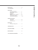
LIST OF MATERIALS ................................................................. 4 INSTALLATION Ducting Calculation Sheet ....................................... Mounting Height & Clearance................................ Ducting Options ........................................................... Specifications ............................................................... Electrical ......................................................................... Cabinet Preparation & Installation ...........
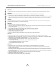
www.zephyronline.com Important Safety Notice READ AND SAVE THESE INSTRUCTIONS WARNING TO REDUCE THE RISK OF FIRE OR ELECTRIC SHOCK, DO NOT USE THIS FAN WITH ANY SOLID-STATE CONTROL DEVICE. WARNING TO REDUCE THE RISK OF FIRE ELECTRIC SHOCK, OR INJURY TO PERSONS, OBSERVE THE FOLLOWING: a. Use this unit only in the manner intended by the manufacturer, if you have questions, contact the manufacturer. b.
TO REDUCE THE RISK OF FIRE, USE ONLY METAL DUCTWORK. NOT FOR USE OVER AN OUTDOOR GRILL CAUTION To reduce risk of fire and to properly exhaust air outside - Do not vent exhaust air into spaces within walls, ceilings, attics, crawl spaces or garages. OPERATION Always leave safety grilles and filters in place. Without these components, operating blowers could catch onto hair, fingers and loose clothing.
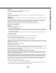
List of Materials www.zephyronline.
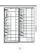
Equivalent number length x used = Duct pieces Total Total 3-1/ 4” x 10” 1 Ft. Rect., straight x( ) = Ft. 6” Round 30 Ft. wall cap with damper x( ) = Ft. 6” Round, straight 1 Ft. x( ) = Ft. 6” Round, roof cap x( ) = Ft. 7”-10” Round, 1 Ft. x( ) = Ft. 6” round to 1 Ft. 3-1/ 4” x 10” rect. transition x( ) = Ft. 3-1/ 4” x 10” 15 Ft. Rect.90 0 elbow x( ) = Ft. x( ) = Ft. 3-1/ 4” x 10” 9 Ft. Rect.45 0 elbow x( ) = Ft. 6” round to 16 Ft. 3-1/ 4” x 10” rect.
Installation – Mounting Height & Clearance www.zephyronline.com Minimum mount height between range top to hood bottom should be no less than 26”. Maximum mount height should be no higher than 36”. It is important to install the hood at the proper mounting height. Hoods mounted too low could result in heat damage and fire hazard; while hoods mounted too high will be hard to reach and will lose its performance and efficiency.
NEVER exhaust air or terminate duct work into spaces between walls, crawl spaces, ceiling, attics or garages. All exhaust must be ducted to the outside. Use single wall rigid metal ductwork only. Fasten all connections with sheet metal screws and tape all joints with certified Silver Tape or Duct Tape. Some Ducting Options side wall cap w/ gravity damper side wall cap w/ gravity damper Soffit or crawl space 8” round or 3-1/4”x10” rect.
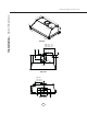
22 ” 12 -3/ 8” ,2 8- 3/8 ”, 34 -3/ 3” 28 8” re an m te ote nn a -3/ 8” ,3 4- 3/8 ”, 40 -3/ 12” 22 8” -1 /2” 3/4 View elec. k/o Ø 73 /4 ” C/L Top View (28”)9” (34”)12” (40“)15” 3-1/4” C/L 9-7/8” Back View 8 5-1/2” 7-3/4” elec. k/o 2” (28”)9” (34”)12” (40“)15” 1-1/2” 5-5/8” (28”)14-1/4” (34”)17-1/4” (40“)20-1/4” 10-3/8” Installation – Specifications www.zephyronline.
WARNING All Electrical work must be performed by qualified electrician or person with similar technical know how and background. For personal safety, remove house fuse or open circuit breaker before beginning installation. Do not use extension cord or adapter plug with this appliance. Follow national electrical codes or prevailing local codes and ordinances.
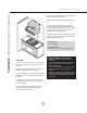
! CAUTION: At least two installers are required due to the weight and size of the liner. If possible, power up and test all functions prior to installation. 1. Remove all packing materials and protective film prior to installation. Use caution during installation to prevent scratches or damage to the stainless steel. 2. Cut out an opening in the bottom of the cabinet by following the dimensions in FIG. 1.
1 1 2 2 2. Remove grease tray by: 1) Pulling up on tray to release from bottom panel. 2) Lifting tray out of liner body. 1. Remove baffle filters by: 1) Pulling filter toward front of liner. 2) Pivoting rear of filter down. 1 Bottom Panel Screws 2 Locking Tabs 4. Remove bottom panel by: 1) Removing (2) screws from left and right sides of bottom panel. 2) Pulling bottom panel toward front of liner to release from locking tabs. 3.
Installation – Horizontal Ducting Preparation www.zephyronline.com 1 1 1 2 2 2. Remove grease tray by: 1) Pulling up on tray to release from bottom panel. 2) Lifting tray out of liner body. 1. Remove baffle filters by: 1) Pulling filter toward front of liner. 2) Pivoting rear of filter down. 1 Bottom Panel Screws 2 Locking Tabs 4. Remove bottom panel by: 1) Removing (2) screws from left and right sides of bottom panel. 2) Pulling bottom panel toward front of liner to release from locking tabs.
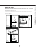
A Round ducting B A C B C 7. Using a flat head screwdriver, remove 8” round or 3 1/4”x10” rect. knock-out plates at the back of the liner. 8. Remove knock-outs A and B for rectangular ducting. Remove knock outs B and C for round ducting. At this point, install the liner into the cabinet by following the steps on Page 10, Step 4. After liner installation, continue to page 14. 9. Place top rectangular cover plate over opening on top of the liner.
Installation – Horizontal Ducting Preparation www.zephyronline.com 10. (Rectangular Ducting) From inside the liner, push 3-1/4” x 10” rectangular adaptor through the back knock-out and secure to interior back wall of liner with (8) M4 x 6mm screws. 10. (Round Ducting) From inside the liner, push 8” round adaptor through the back knock-out and secure to interior back wall of liner with (4) M4 x 6mm screws. 2 1 11.
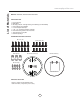
Display (speed level, delay off, filter clean/change,clean air) clean mesh filter clean air replace charcoal filter Adjust 6 Speed Levels Lights On/Dim/Off 1 Power / Delay Off Button Power Button Function Button will turn power on and off for entire hood (fan and lights). - Hood will remember the last speed and light level it was turned off at. (Example: Press Button to turn off hood when on fan speed 4 and high lights. Press Button again and the hood will turn back on at speed 4 and high lights level.
Features & Controls – User Interface www.zephyronline.com Mesh Filter Clean Indicator (always enabled) - After 30 hours of fan usage the Graphic and words “clean mesh filter” will illuminate indicating it is time to clean the mesh filters. Graphic and words will remain illuminated until reset. - To reset: With liner off, hold the Button for three seconds, after three seconds the Graphic and words “clean mesh filter” will turn off and the 30 hour timer will reset.
SYNCHRONIZATION: To create a unique link between your range hood and remote control please follow the below steps: 1. With range hood off, press and hold the “lights” button on the range hood until the LCD screen blinks on and off. 2. Press the “lights” button on the remote, the lights on the hood will turn on. The synchronization is complete.
Maintenance – Cleaning and Installing Filters www.zephyronline.com SURFACE MAINTENANCE: Clean periodically with hot soapy water and clean cotton cloth. Do not use corrosive or abrasive detergent, or steel wool/ scoring pads which will scratch and damage surface. Do not use products containing chlorine bleach or orange cleaners. For heavier soil use liquid degreaser. After cleaning, you may use non-abrasive stainless steel polish/ cleaners, to polish and buff out the stainless luster and grain.
Issue Cause What to do After installation, the unit doesn’t work. 1. The power source is not turned ON. 1. Make sure the circuit breaker and the unit’s power is ON. 2. The power line and the cable locking connector is not connecting properly. 2. Check the power connection with the unit is connected properly. 3. The switch board and control board wires are disconnected. 3. Make sure the wires between the switch board and control board are connected properly. 4. The wires on control board are loose.
Fan Curve Diagrams www.zephyronline.com Airflow Control Technology (ACT) Some local codes limit the maximum amount of CFM a range hood can move. ACT allows you to control the maximum blower CFM of hoods with Zephyr’s DCBL Suppression System without the need for expensive make up air kits. ACT enables the installer to easily set the maximum blower speed to one of three most commonly specified CFM levels; 590, 440 or 290 CFM. The usage of ACT may not be necessary for your installation.
21 Fan Curve Diagrams
Wiring Diagrams www.zephyronline.com Model: AK9428AS / AK9434AS Voltage: 120V 60Hz Power consumption Total: Max. 219W @ 3.5A Lamp: Max. 6Wx2 Fan: Max. 207W Electronically Protected U V W V01 U V W 5A 250V AC-N ON/OFF DOWN UP AC-L LAMP Power consumption shown for default 715 CFM blower configuration Model: AK9440AS Voltage: 120V 60Hz Power consumption Total: Max. 225W @ 3.6A Lamp: Max. 6Wx3 Fan: Max.
PART # Replacement Parts AK9428AS / AK9434AS / AK9440AS Baffle Filter, Large (each) 50210013 AK9434AS Baffle Filter, Small (each) 50210017 RF Remote Control 14000005 To order parts, visit us online at http://store.zephyronline.com or call us at 1.888.880.
STAPLE YOUR RECEIPT HERE Proof of the original purchase date is needed to obtain service under warranty Limited Warranty TO OBTAIN SERVICE UNDER WARRANTY OR FOR ANY SERVICE RELATED QUESTIONS, please call: 1-888-880-8368 Zephyr Corporation (referred to herein as “we” or “us”) warrants to the original consumer purchaser (referred to herein as “you” or “your”) of Zephyr products (the “Products”) that such Products will be free from defects in materials or workmanship as follows: Three Year Limited Warranty
Guide d’utilisation, d’entretien et d’installation www.zephyronline.com Monsoon DCBL AK9428AS AK9434AS AK9440AS Numéro de modèle Numéro de série Date d’achat Détaillant JUL12.
www.zephyronline.
LISTE DU MATÉRIEL ................................................................. 4 INSTALLATION Feuille de calcul pour le conduit ........................... Espace libre et hauteur de montage ................... Options d’installation pour le conduit .................. Spécifications ............................................................... Électricité ........................................................................ Préparation et installation des armoires ............
www.zephyronline.com Mise en garde de sécurité LISEZ ET CONSERVEZ CES INSTRUCTIONS AVERTISSEMENT POUR RÉDUIRE LES RISQUES D’INCENDIE OU DE DÉCHARGE ÉLECTRIQUE, N’UTILISEZ PAS CET APPAREIL AVEC UN TABLEAU DE COMMANDE À SEMI-CONDUCTEURS. AVERTISSEMENT POUR RÉDUIRE LES RISQUES D’INCENDIE, DE DÉCHARGE ÉLECTRIQUE OU DE BLESSURE, RESPECTEZ CES CONSIGNES : a. N’utilisez cet appareil que de la manière prévue par le fabricant. Si vous avez des questions, communiquez avec le fabricant. b.
POUR RÉDUIRE LES RISQUES D’INCENDIE, N’UTILISEZ QUE DES CONDUITS D’AÉRATION EN MÉTAL. CETTE HOTTE N’EST PAS CONÇUE POUR UNE UTILISATION AVEC UN GRIL EXTÉRIEUR ATTENTION To reduce risk of fire and to properly exhaust air outside - Do not vent exhaust air into spaces within walls, ceilings, attics, crawl spaces or garages. OPERATION Pour réduire les risques d’incendie et pour évacuer l’air convenablement, assurez-vous de canaliser l’air à l’extérieur de la maison.
Liste du matériel www.zephyronline.
pi 3-1/ 4” x 10” 1 pi rect., droit x( 6” circ., droit 1 pi x( ) = pi 7” circ., droit 1 pi x( ) = pi 3-1/ 4” x 10” 15 pi rect., coude à 90º x( ) = pi 3-1/ 4” x 10” 9 pi rect., coude à 45º x( ) = pi 3-1/ 4” x 10” 24 pi rect., coude plat à 90º x( 3-1/ 4” x 10” 30 pi x( ) = Longueur x Nombre utilisé Pièces de conduit Total Total 30 pi x( ) = pi 6” chapeau de toiture circ. 30 pi x( ) = pi 6” circ. à rect. de 3-1/4" x 10" 1 pi x( ) = pi 6” circ. à 16 pi rect.
Installation – Espace libre et hauteur de montage www.zephyronline.com Si des changements de direction ou des adaptateurs sont nécessaires, installez-les le plus loin possible de l’ouverture et le plus éloigné possible – séparés par au moins une pièce standard – l’un de l’autre. La hauteur de montage minimale ne devrait pas être moins de 26”. La hauteur de montage maximale ne devrait pas outrepasser 36”. Il est important d’installer la hotte à la hauteur de montage adéquate.
N’évacuez ou ne terminez JAMAIS l’échappement du conduit dans les espaces entre les murs, les vides sanitaires, le plafond, le grenier, ou le garage. Tous les échappements doivent être dirigés à l’extérieur de la maison, à moins que l’option de reprise d’air ne soit utilisée. N’utilisez que des conduits en métal pour cloison simple. Fixez toutes les pièces du conduit avec des vis à tôle et isolez tous les joints avec du ruban adhésif en toile ou du ruban réflecteur certifié.
22 -3 / ” 12 8“ ,2 8- 3 /8 ”, 34 - 3/ 3” 28 - 3/ 8” 12” 8” ,3 4- 3/8 ”, 40 -3/ 22 8” ” 1 /2 Vue 3/4 Entrée dèfonçable Ø 73 L/C Vue de haut (28”) 9” (34”) 12” (40“) 15” L/C 9-7/8” Vue arrière 8 5-1/2” 3-1/4” 7-3/4” /4 ” 2” (28”) 9” (34”) 12” (40“) 15” 1-1/2” 5-5/8” (28”) 14-1/4” (34”) 17-1/4” (40“) 20-1/4” 10-3/8” Installation – Spécifications de la hotte www.zephyronline.
AVERTISSEMENT Tous les travaux électriques doivent être réalisés par un électricien qualifié ou par une personne possédant l’expérience technique et le savoir-faire nécessaire. Pour votre sécurité, enlevez le fusible ou ouvrez le disjoncteur de circuit avant de commencer l’installation. N’utilisez pas de cordon prolongateur ou de fiche d’adaptation avec cet appareil. Suivez les codes et réglementations nationaux ou locaux en vigueur.
! ATTENTION: Compte tenu du poids et des dimensions de la hotte, au moins deux installateurs sont nécessaires. Dans la mesure du possible, allumez l’appareil et assurez-vous du bon fonctionnement de toutes les fonctions avant de procéder à l’installation. 1. Enlevez tout le matériel d’emballage et la pellicule de protection avant de procéder à l’installation. Pour éviter d’égratigner ou d’endommager l’acier inoxydable, faites preuve de prudence durant l’installation. 3.
1 1 2 2 1. Enlevez les filtres déflecteurs de la façon suivante : (1) 2. Enlevez le collecteur de graisse de la façon suivante : Tirez le filtre vers l’avant du boîtier. (2) Faites pivoter l’arrière du filtre vers le bas. (1) Poussez le collecteur vers le haut pour le libérer du panneau inférieur. (2) Retirez le collecteur du boîtier. 1 Vis du panneau inférieur 2 Languettes de verrouillage 3. (le cas échéant) Enlevez les panneaux d’habillage 4.
Installation – Préparation pour le conduit horizontal www.zephyronline.com 1 1 1 2 2 1. Enlevez les filtres déflecteurs de la façon suivante : (1) 2. Enlevez le collecteur de graisse de la façon suivante : Tirez le filtre vers l’avant du boîtier. (2) Faites pivoter l’arrière du filtre vers le bas. (1) Poussez le collecteur vers le haut pour le libérer du panneau inférieur. (2) Retirez le collecteur du boîtier. 1 Vis du panneau inférieur 2 Languettes de verrouillage 3.
A B Conduit circulaire C A B C 7. À l’aide d’un tournevis plat, enlevez l’entrée 8. Enlevez les entrées défonçables A et B pour installer défonçable circulaire de 8” ou l’entrée défonçable rectangulaire de 3 1/4”x10”, toutes deux situés à l’arrière du boîtier. 9. Placez la plaque supérieure rectangulaire sur un conduit rectangulaire. Enlevez les entrées défonçables B et C pour installer un conduit circulaire.
Installation – Préparation pour le conduit horizontal www.zephyronline.com 10. (Conduit rectangulaire) À partir de l’intérieur du boîtier, installez l’adaptateur rectangulaire de 3-1/4” x 10” dans l’entrée défonçable arrière et fixez-le à la paroi intérieure arrière du boîtier à l’aide de (8) vis M4 x 6 mm. 10.
Affichage (vitesse, arrêt automatique, nettoyage/changement des filtres, purification d’air) clean mesh filter clean air replace charcoal filter Choix de six vitesses Lumières : Allumer/Veilleuse/Éteindre 1-Touche de mise en marche/arrêt automatique Fonction de mise en marche - La touche permet d’allumer et d’éteindre la hotte (ventilateur et lumières).
Commandes – Interface utilisateur www.zephyronline.com Indicateur de nettoyage des filtres à tamis (toujours en fonction) - Après 30 heures d’utilisation du ventilateur, le symbole et les mots « clean mesh filter » s’illuminent, indiquant qu’il est temps de nettoyer les filtres à tamis. Le symbole et les mots restent illuminés jusqu’à la réinitialisation de la fonction. - Pour réinitialiser : Lorsque la hotte est éteinte, appuyez et tenez la touche enfoncée pendant trois secondes.
Synchronisation: Pour créer un lien unique entre votre hotte et la télécommande s’il vous plaît suivez les étapes ci-dessous: 1. Avec la hotte hors tension, appuyez et maintenez le touche «Lights» sur la hotte jusqu’à ce l’écran LCD clignote sur et en dehors. 2. Appuyez sur la touche «Lights» de la télécommande, les feux sur le capot se mettra en marche. La synchronisation est terminée.
Entretien – Installation et nettoyage des filtres www.zephyronline.com ENTRETIEN DES SURFACES: Nettoyez régulièrement les surfaces de la hotte avec de l’eau savonneuse chaude et un chiffon de coton propre. N’utilisez pas de détergent abrasif ou corrosif, de laines d’acier ou de tampons à récurer; ils égratigneront et endommageront les surfaces. N’utilisez pas de produits à blanchir au chlore ou d’agents nettoyants « orange ». Pour les taches plus tenaces, utilisez du produit dégraissant liquide.
Problème Cause Solution Après l’installation, l’appareil ne fonctionne pas. 1. Le bloc d’alimentation n’est pas allumé 1. Assurez-vous que l’alimentation du disjoncteur et de l’appareil est allumée 2. La ligne électrique et le raccord de câble ne sont pas correctement branchés 2. Vérifiez que le branchement de l’appareil a été fait correctement 3. Les fils électriques du tableau de contrôle et de commande sont débranchés 3.
Tableau De Rendement Du Ventilateur www.zephyronline.com Débit d’air contrôle de la technologie (ACT) Certains codes locaux de limiter le montant maximum de CFM qu’une hotte de cuisinière peut se déplacer. ACT vous permet de contrôler le maximum CFM de les hottes avec le système de répression DCBL à partir de Zephyr sans avoir besoin de coûteux kits pour l’air de remplacement.
21 Tableau De Rendement Du Ventilateur
Schéma de circuits Modèle AK9428AS / AK9434AS Tension 120V 60Hz Consommation d’énergie Total: Max. 219W @ 3.5A Lampe: Max. 6Wx2 Ventilateur Max. 207W Protégé électroniquement Moteur DEL DEL CONTRÔLE CONNEXION U V DEL W 5A 250V AC-N AC-L Boîtier ON/OFF DOWN UP LAMPE Blanc Noir CONTRÔLE ACB Vert W V01 U V Consommation montré pour défaut de configuration du ventilateur 715 CFM Schéma de circuits Modèle AK9440AS Tension 120V 60Hz Consommation d’énergie Total: Max. 225W @ 3.6A Lampe: Max.
Nº DE PIÈCE Pièces de remplacement Filtre déflecteur pour AK9428AS/AK9434AS/AK9440AS, grand (chaque) 50210013 Filtre déflecteur pour AK9434AS, petit (chaque) 50210017 Commande à distance RF 14000005 Pour commander des pièces, visitez-nous en ligne au www.zephyronline.
AGRAFEZ VOTRE REÇU ICI Garantie limitée Une preuve de la date d’achat originale est nécessaire pour obtenir du service lorsque le produit est sous garantie POUR OBTENIR DU SERVICE SOUS GARANTIE OU POUR TOUTE QUESTION LIÉE À L’ENTRETIEN, veuillez communiquer avec nous au 1-888-880-8368 Zephyr Corporation (désigné aux présentes sous le nom de « nous ») garantit au premier acheteur (désigné aux présentes sous le nom de « vous » ou « votre ») de produits Zephyr (les « Produits ») que lesdits produits sont ex