Use, Care, and Installation Guide www.zephyronline.com Tornado II AK8200AS Tornado III AK8300ASX Model number: Serial Number: Date of Purchase: Sales Dealer: APR14.
www.zephyronline.
INSTALLATION Ducting Calculation Sheet ....................................... Mounting Height & Clearance................................ Ducting Options ........................................................... 6SHFL¿FDWLRQV ............................................................... Electrical ......................................................................... Installing the Power Pack ........................................ Single and Dual Internal Blowers .........................
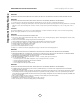
www.zephyronline.com Important Safety Notice READ AND SAVE THESE INSTRUCTIONS WARNING TO REDUCE THE RISK OF FIRE OR ELECTRIC SHOCK, DO NOT USE THIS FAN WITH ANY SOLID-STATE CONTROL DEVICE. WARNING TO REDUCE THE RISK OF FIRE ELECTRIC SHOCK, OR INJURY TO PERSONS, OBSERVE THE FOLLOWING: a. Use this unit only in the manner intended by the manufacturer, if you have questions, contact the manufacturer. b.
TO REDUCE THE RISK OF FIRE, USE ONLY METAL DUCTWORK. NOT FOR USE OVER AN OUTDOOR GRILL CAUTION 7R UHGXFH ULVN RI ¿UH DQG WR SURSHUO\ H[KDXVW DLU RXWVLGH 'R QRW YHQW H[KDXVW DLU LQWR VSDFHV ZLWKLQ ZDOOV FHLOLQJV attics, crawl spaces or garages. OPERATION $OZD\V OHDYH VDIHW\ JULOOHV DQG ¿OWHUV LQ SODFH :LWKRXW WKHVH FRPSRQHQWV RSHUDWLQJ EORZHUV FRXOG FDWFK RQWR KDLU ¿QJHUV and loose clothing.
List of Materials www.zephyronline.
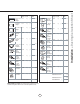
Equivalent number length x used = Duct pieces Total Total 3-1/ 4” x 10” 1 Ft. Rect., straight x( ) = Ft. 6” Round 30 Ft. wall cap with damper x( ) = Ft. 6” Round, straight 1 Ft. x( ) = Ft. 6” Round, roof cap x( ) = Ft. 7”-10” Round, 1 Ft. x( ) = Ft. 6” round to 1 Ft. 3-1/ 4” x 10” rect. transition x( ) = Ft. 3-1/ 4” x 10” 15 Ft. Rect.90 0 elbow x( ) = Ft. x( ) = Ft. 3-1/ 4” x 10” 9 Ft. Rect.45 0 elbow x( ) = Ft. 6” round to 16 Ft. 3-1/ 4” x 10” rect.
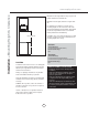
Installation – Mounting Height & Clearance www.zephyronline.com Minimum mount height between range top to hood ERWWRP VKRXOG EH QR OHVV WKDQ ´ Maximum mount height should be no higher than ´ It is important to install the hood at the proper mounting height.
NEVER exhaust air or terminate duct work into spaces between walls, crawl spaces, ceiling, attics or garages. All exhaust must be ducted to the outside. Use metal ductwork only.
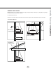
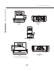
Installation – 6SHFL¿FDWLRQV www.zephyronline.com 24 5/8” 14 3/4” 5” 7 3/4” 1 1/2” 29 13/16” AK8200AS front 1 5/16” elec. k/o 25 15/16” 6 1/2” CL 14 11/16” 15 13/16” 11 7/16” 2 3/8” 4 3/4” 11 7/16” CL 4 3/8” AK8200AS top 13/16” 11 7/16” 2 5/8” 14 11/16” 15 13/16” AK8200AS/AK8300ASX side 33 1/8” 14 3/4” *7 3/4” 14 11/16” 15 13/16” B A 4 1/2” CL 6 1/2” 11 7/16” 4 3/4” 2 3/8” 11 7/16” *5” CL 2 5/8” A: elec. B: ext.
WARNING $OO (OHFWULFDO ZRUN PXVW EH SHUIRUPHG E\ TXDOL¿HG HOHFWULFLDQ RU SHUVRQ ZLWK VLPLODU WHFKQLFDO NQRZ how and background. For personal safety, remove house fuse or open circuit breaker before beginning installation. Do not use extension cord or adapter plug with this appliance. Follow national electrical codes or prevailing local codes and ordinances.
! CAUTION: At least two installers are required due to the weight and size of the hood. AK8200AS AK8300ASX 26 1/16” 34 11/16” C/L 1. Install blower into Power Pack AK8200AS - Blower is pre-installed AK8300ASX - Refer to page 11 for instructions Remove support screw from top of Power Pack before installing into cabinet. FIG 2b 14 3/4” Installation – Installing the Power Pack www.zephyronline.
FOR REMOTE BLOWER PREPARATION INSTRUCTIONS TURN TO PAGE 12. 2. Connect 6 pin male connector from blower wiring to 6 pin female connector in the power SDFN SOXJ LV ORFDWHG LQVLGH WKH SRZHU SDFN SURWUXGLQJ IURP WKH ZKLWH FRQWURO ERDUG ER[ 1. Position blower plate over bracket on inside back of hood and pivot up. Secure plate to hood ZLWK [ ´ VFUHZV EORZHU SLFWXUHG LV D 3%, $ 3. Single Blower ± &RQQHFW ´ URXQG GXFW ZRUN WR blower collar.
Installation – Remote Blower Preparation www.zephyronline.com B 3ODFH ´ URXQG DGDSWHU RQ WRS RI SRZHU SDFN DQG VHFXUH ZLWK 0 [ VFUHZV &RQQHFW ´ URXQG GXFW ZRUN WR ´ URXQG DGDSWHU 2. Install threaded end of remote blower wiring through external blower wiring knock out (B) located in junction box on top of power pack. B 4.
3 5 Min Delay Off 5 Display (Speed level, Delay Off Indicator) 1 Blower On/Off 2 Adjust 3 Speed Levels 1 Blower On/Off By pressing , the blower is switched On and Off. When switched on, the blower turns on at the same speed it was switched off at. When switched off the entire hood powers off, including the lights. 2 Speed Selection The 3 speed levels are selected by pressing to decrease and to increase speed level. The display indicates speed level selected.
Features & Controls – Touch Controls www.zephyronline.com Baffle Filter Clean Reminder Whether your hood is installed as an exhaust or purifying unit, a set if baffle filters are fitted by the factory, These baffle filters are intended to filter out residue from cooking. They need not be replaced on a regular basis but are required to be kept clean.
UHVSRQVLEOH IRU FRPSOLDQFH FRXOG YRLG WKH XVHU¶V DXWKRULW\ WR RSHUDWH WKLV HTXLSPHQW ([DPSOH XVH RQO\ VKLHOGHG LQWHUIDFH cables when connecting to computer or peripheral device. This device complies with Part 15 of the FCC Rules. Operation is VXEMHFW WR WKH IROORZLQJ WZR FRQGLWLRQV 7KLV GHYLFH PD\ QRW FDXVH KDUPIXO LQWHUIHUHQFH DQG 7KLV GHYLFH PXVW DFFHSW any interference received, including interference that may cause undesired operation.
Maintenance – Cleaning and Installing Filters www.zephyronline.com SURFACE MAINTENANCE: Clean periodically with hot soapy water and clean cotton cloth. Do not use corrosive or abrasive detergent, or steel wool/ scoring pads which will scratch and damage surface. Do not use products containing chlorine bleach or orange cleaners. For heavier soil use liquid degreaser.
CAUTION: Light bulb becomes extremely hot when turned on. DO NOT touch bulb until switched off and cooled. Touching hot bulbs could cause serious burns. Make sure all power is turned off and bulbs are not hot. Remove by turning bulb counter clockwise. Note: Bulb does not unscrew; it turns 60 degrees, stops and falls out. ,I EXOEV DUH GLI¿FXOW WR WXUQ GXH WR SURORQJHG XVH ¿UPO\ DWWDFK D JODVV VXFWLRQ FXS DSSUR[LPDWHO\ WKH diameter of the bulb or use a rubber/latex glove and turn counter clockwise.
Troubleshooting www.zephyronline.com TROUBLESHOOTING PROCEDURES FOR TORNADO II AND TORNADO III Issue Cause What to do After installation, the unit doesn’t work. 1. The power source is not turned ON. 1. Make sure the circuit breaker and the unit’s power is ON. 2. The power line and the cable locking connector is not connecting properly. 2. Check the power connection with the unit is connected properly. 3. The switch board and control board wirings are disconnected. 3.
PART # Replacement Parts /LJKW %XOE 05 *8 : HDFK %DIÀH )LOWHU HDFK Remote Control = % 14000005 Optional Accessories /LQHU ´ /LQHU ´ /LQHU ´ /LQHU ´ /LQHU ´ $. $6 $. $6 $. $6; $. $6; $. $6; $.
STAPLE YOUR RECEIPT HERE Proof of the original purchase date is needed to obtain service under warranty Limited Warranty TO OBTAIN SERVICE UNDER WARRANTY OR FOR ANY SERVICE RELATED QUESTIONS, please call: 1-888-880-8368 Zephyr Corporation (referred to herein as “we” or “us”) warrants to the original consumer purchaser (referred to herein as “you” or “your”) of Zephyr products (the “Products”) that such Products will be free from defects in materials or workmanship as follows: Ten Year Limited Warranty fo