
Installation guide


www.zephyronline.com
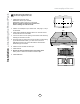
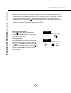
1. Place 8” round adapter on top of power pack
and secure with (4) M4x8 screws. Connect 8”
round duct work to 8” round adapter.
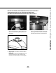
2. Install threaded end of remote blower wiring
through external blower wiring knock out
located in junction box on top of power pack.
3. Place cap over threaded end of remote blower
wiring and secure by turning clockwise.
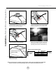
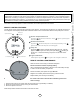
4. Connect 6 pin male connector from blower
wiring to 6 pin female connector in the power
pack. (plug is located inside the power pack
protruding from the white control board box).
A - elec k/o
B - ext blower k/o
A
B
A - elec k/o
B - ext blower k/o
A
B
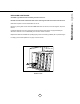
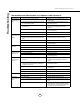
CBE-1000 / PBN-1000A: WIRING DIAGRAM
White (common)
Black (high)
Blue (med)
Red (low)
Green (ground)
Remote Blower
Wiring Box
(hood)
Junction Box
(Remote Blower)
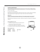
A
A: Ground wire screw
location (inside)
5. Secure green ground wire from remote
blower wiring to ground screw located
inside the power pack