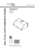
Use, Care, and Installation Guide www.zephyronline.com Tempest I AK7000AS AK7036AS AK7042AS Model number: Serial Number: Date of Purchase: Sales Dealer: MAY12.
www.zephyronline.
INSTALLATION Ducting Calculation Sheet ....................................... Mounting Height & Clearance................................ Ducting Options ........................................................... Specifications ............................................................... Mounting the Range Hood ...................................... Horizontal Conversion............................................... PBD-1100A Dual Blower ..........................................
www.zephyronline.com Important Safety Notice READ AND SAVE THESE INSTRUCTIONS WARNING TO REDUCE THE RISK OF FIRE OR ELECTRIC SHOCK, DO NOT USE THIS FAN WITH ANY SOLID-STATE CONTROL DEVICE. WARNING TO REDUCE THE RISK OF FIRE ELECTRIC SHOCK, OR INJURY TO PERSONS, OBSERVE THE FOLLOWING: a. Use this unit only in the manner intended by the manufacturer, if you have questions, contact the manufacturer. b.
TO REDUCE THE RISK OF FIRE, USE ONLY METAL DUCTWORK. CAUTION To reduce risk of fire and to properly exhaust air outside - Do not vent exhaust air into spaces within walls, ceilings, attics, crawl spaces or garages. No for use over an outdoor grill. OPERATION Always leave safety grilles and filters in place. Without these components, operating blowers could catch onto hair, fingers and loose clothing.
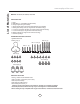
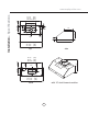
List of Materials www.zephyronline.
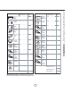
Equivalent number length x used = Duct pieces Total Total 3-1/ 4” x 10” 1 Ft. Rect., straight x( ) = Ft. 6” Round 30 Ft. wall cap with damper x( ) = Ft. 6” Round, straight 1 Ft. x( ) = Ft. 6” Round, roof cap x( ) = Ft. 7”-10” Round, 1 Ft. x( ) = Ft. 6” round to 1 Ft. 3-1/ 4” x 10” rect. transition x( ) = Ft. 3-1/ 4” x 10” 15 Ft. Rect.90 0 elbow x( ) = Ft. x( ) = Ft. 3-1/ 4” x 10” 9 Ft. Rect.45 0 elbow x( ) = Ft. 6” round to 16 Ft. 3-1/ 4” x 10” rect.
Installation – Mounting Height & Clearance www.zephyronline.com Minimum mount height between range top to hood bottom should be no less than 26”. Maximum mount height should be no higher than 36”. It is important to install the hood at the proper mounting height. Hoods mounted too low could result in heat damage and fire hazard; while hoods mounted too high will be hard to reach and will lose its performance and efficiency.
NEVER exhaust air or terminate duct work into spaces between walls, crawl spaces, ceiling, attics or garages. All exhaust must be ducted to the outside. Use metal ductwork only. Fasten all connections with sheet metal screws and tape all joints with certified Silver Tape or Duct Tape.
2” 13 3/16” 3” 7/ 12” 11” 8” elec k/o 3” 29 15/16” 35 15/16” 41 15/16” 22 1/2” (30”) (36”) (42”) side top 14 3/1 6” 10 ” 3/8 2 3/4” CL ø 9 15/16” 2 3/16” 1 3/16” 1 3/16” 27 7/8” (30”) (36”) 33 7/8” 39 13/16” (42”) 15 5/16” ø5 6 7/16” 5 9/16” 8 9/16” 1 1/8” 27 7/8” (30”) 33 7/8” (36”) 39 13/16” (42”) CL 8 9/16” Installation – Specifications www.zephyronline.
WARNING All Electrical work must by performed by qualified electrician or person with similar technical know how and background. For personal safety, remove house fuse or open circuit breaker before beginning installation. Do not use extension cord or adapter plug with this appliance. Follow national electrical codes or prevailing local codes and ordinances.
Installation – Mounting the Range Hood www.zephyronline.com For dual blower installation instructions please refer to page 13. If recirculating range hood refer to the manual included with ZRC-07xx recirculating kit or on our website prior to installing hood. Recirculating kit compatible with 600cfm single internal blower only. 5. Duct opening cutout For Mounting Under a Kitchen Cabinet 1. Select preferred duct location (vertical or horizontal). duct/silver tape 2.
VERTICAL TO HORIZONTAL DUCTING CONVERSION 1. Disconnect blower wire. 2. Remove support screw from top of hood near the back. Remove 2 screws holding blower plate to hood and pull blower towards front of hood to release from internal bracket. 3. Unscrew (4) screws holding blower to blower plate and remove blower. 4. Cover round blower opening on blower plate with 6” round metal cap. Attach with (3) 3.5x8 screws. 5. Re-attach blower plate to hood by following removal instructions in reverse.
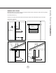
Installation – Horizontal Conversion www.zephyronline.com 6. On the back of the hood, remove the (6) screws holding the rectangular cap. 7. Place round to rectangular transition adapter inside hood and line it up with the rectangular opening. Attach with (4) M4x8 screws from the outside. 8. Picture of round to rectangular transition adapter installed in hood. 9. Attach blower brackets to blower using (2) 10x3/16” screws on each bracket. 10.
*IMPORTANT: Dual blower and heat lamps may only be used together in 42” models. 30” and 36” models will only accommodate one or the other, not both at the same time. 1. Disconnect single blower wire. 2. Remove support screw from top of hood near the back. Remove 2 screws holding blower plate to hood to release blower plate from hood body. 3. Remove (4) screws holding blower to blower plate and remove blower. Remove capactor from blower plate. Remove and discard metal damper and blower plate. 4.
Installation – PBD-1100A Dual Blower www.zephyronline.com 8. Place 10” round adapter (included with PBD1100A) on top of hood and secure with (4) M4x8 screws. Connect 10” duct work. 7. Secure dual blower plate to hood by following removal instructions in reverse. Attach blower wire to hood. The 10” round adapter is fitted with a metal damper to prevent outside airflow from entering the kitchen. The 6” round single blower is also fitted with a metal damper.
*IMPORTANT: Dual blower and heat lamps may only be used together in 42” models. 30” and 36” models will only accommodate one or the other, not both at the same time. 1. Remove nuts from each of the (4) screws around the bottom panel. Remove bottom panel. 2. Replace bottom panel with heat lamp bottom panel. Re-attach screws and nuts. 3. Place heat lamp housings over the (4) prethreaded screw posts inside the hood. Attach with screws provided. 4.
Features & Controls – Touch Controls & Features www.zephyronline.com 4 Lights On/Dim/Off 3 5 Min Delay Off 5 Display (Speed level, Delay Off Indicator) 1 Blower On/Off 2 Adjust 3 Speed Levels 1 Blower On/Off By pressing , the blower is switched On and Off. When switched on, the blower turns on at the same speed it was switched off at. When switched off the entire hood powers off, including the lights.
The filter change reminder function in the microprocessor needs to be switched on. When switched on, the microprocessor will elapse and count usage time and indicate by a flashing C when charcoal filter replacements are needed. Setting the Filter Change Reminder When off, hold for approximately 5 seconds. The display will change from (exhaust mode) to C (recirculating mode) this indicates that the elapse timer function is switched on and charcoal filters are used. Set Mode hold 5 sec.
Features & Controls – Touch Controls & Features www.zephyronline.com Baffle Filter Clean Reminder Whether your hood is installed as an exhaust or purifying unit, a set if baffle filters are fitted by the factory, These baffle filters are intended to filter out residue from cooking. They need not be replaced on a regular basis but are required to be kept clean.
Clean periodically with hot soapy water and clean cotton cloth. Do not use corrosive or abrasive detergent, or steel wool/scouring pads which will scratch and damage surface. Do not use products containing chlorine bleach or orange cleaners. For heavier soil use liquid degreaser. After cleaning, you may use non-abrasive stainless steel polish/ cleaners, to polish and buff out the stainless luster and grain. Always scrub lightly using a micro fiber or clean cotton cloth and with grain.
Maintenance – Lights www.zephyronline.com REPLACING LIGHT BULBS CAUTION: Light bulb becomes extremely hot when turned on. DO NOT touch bulb until switched off and cooled. Touching hot bulbs could cause serious burns. Make sure all power is turned off and bulbs are not hot. Remove by turning bulb counter clockwise. Note: Bulb does not unscrew; it turns 60 degrees, stops and falls out.
Issue Cause What to do After installation, the unit doesn’t work. 1. The power source is not turned ON. 1. Make sure the circuit breaker and the unit’s power is ON. 2. The power line and the cable locking connector is not connecting properly. 2. Check the power connection with the unit is connected properly. 3. The switch board and control board wirings are disconnected. 3. Make sure the wirings between the switch board and control board are connected properly. 4.
List of Parts and Accessories www.zephyronline.
STAPLE YOUR RECEIPT HERE Proof of the original purchase date is needed to obtain service under warranty Limited Warranty TO OBTAIN SERVICE UNDER WARRANTY OR FOR ANY SERVICE RELATED QUESTIONS, please call: 1-888-880-8368 Zephyr Corporation (referred to herein as “we” or “us”) warrants to the original consumer purchaser (referred to herein as “you” or “your”) of Zephyr products (the “Products”) that such Products will be free from defects in materials or workmanship as follows: Ten Year Limited Warranty fo