
User Guide
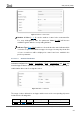
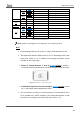
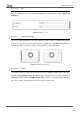
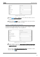
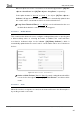
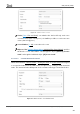

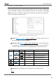
Table Of Contents
- Contents
- Document updates
- 1 Introduction
- 2 Configuration
- 2.1 General
- 2.2 Display
- 2.3 Inputs
- 2.4 Thermostat n
- ANNEX I. Video Intercom Operation
- ANNEX II. Internal Call Operation
- ANNEX III. Remote Control via IP
- ANNEX IV. Graphs
- ANNEX V. Differences with Z50 / Z100
- ANNEX VI. Communication Objects

Z50 / Z70 v2 / Z100
https://www.zennio.com Tecnical Support: https://support.zennio.com
87
Table 4 shows the permitted value range and the name of the object through which the
values are sent to the bus.
Function
Size
Sign
Range
Related Object
Integer
1 Byte
Unsigned
[0…255]
[Ci] 1-Byte Unsigned Int Control
Signed
[-128…0…127]
[Ci] 1-Byte Signed Int Control
2 Bytes
Unsigned
[0…65535]
[Ci] 2-Byte Unsigned Int Control
Signed
[-32768…32767]
[Ci] 2-Byte Signed Int Control
Scaling
1 Byte
[0…100]
[Ci] Percentage Control
Float
2 Bytes
[-671088.64…0…670433.28]
[Ci] 2-Byte Float Indicator
Table 4. Numerical constant controls
Units: permits specifying the measuring units of the displayed value. For
percentage indicators, the symbol % always will be displayed as unit.
2.2.2.1.2.6 Room State
Configuring with this function the box, controlling the states of the room will be possible,
as well as show the associated pop-up. Thus, pressing the button in the box will cause the
room status to switch between normal and Do Not Disturb or Make Up Room.
Figure 73. 1-Button Control - Room State.
State [Make Up Room / Do Not Disturb]: sets the status to be switched together
with Normal. The switched values are sent to the bus via the 1-byte object "[Ci]
Room State".
Show Pop-Up When Activating Normal State [No / Pop-Up 1 / … / Pop-Up 6]:
allows to select the pop-up to be displayed when the normal mode is activated.