
User Guide
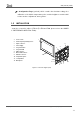
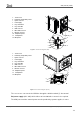
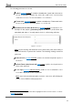
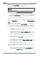
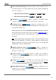
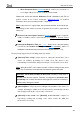
Table Of Contents
- Contents
- Document updates
- 1 Introduction
- 2 Configuration
- 2.1 General
- 2.2 Display
- 2.3 Inputs
- 2.4 Thermostat n
- ANNEX I. Video Intercom Operation
- ANNEX II. Internal Call Operation
- ANNEX III. Remote Control via IP
- ANNEX IV. Graphs
- ANNEX V. Differences with Z50 / Z100
- ANNEX VI. Communication Objects

Z50 / Z70 v2 / Z100
https://www.zennio.com Tecnical Support: https://support.zennio.com
13
to avoid interference to the KNX bus. This external power must be supplied to the device
through the corresponding terminal (4) provided within the original packaging.
Note: although the device will not turn functional until it is powered with the external
supply, the KNX bus power should be enough to perform downloads from ETS
(application program, group addresses, etc.).
A short press on the Prog./Test button (5) will make the device enter the programming
mode. The Prog./Test LED (6) will then light in red. On the contrary, if this button is held
while the device gets connected to the bus, Z70 v2 will enter the safe mode. In such
case, the programming LED will blink in red colour.
Firmware updates (see section 2.1.11) can be performed through the Micro-USB (8)
connector. It is important to take into account that USB memories must be formatted in
FAT32.
For detailed information about the technical features of Z50 / Z70 v2 / Z100, as well as
on security and installation procedures, please refer to the device Datasheet, bundled
within the device packaging and also available at
www.zennio.com.