
User Guide
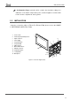
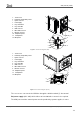
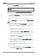
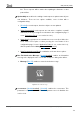
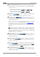
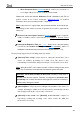
Table Of Contents
- Contents
- Document updates
- 1 Introduction
- 2 Configuration
- 2.1 General
- 2.2 Display
- 2.3 Inputs
- 2.4 Thermostat n
- ANNEX I. Video Intercom Operation
- ANNEX II. Internal Call Operation
- ANNEX III. Remote Control via IP
- ANNEX IV. Graphs
- ANNEX V. Differences with Z50 / Z100
- ANNEX VI. Communication Objects

Z50 / Z70 v2 / Z100
https://www.zennio.com Tecnical Support: https://support.zennio.com
12
Figure 2 Schematic diagram (Z50)
Figure 3 Schematic diagram (Z100)
The screens are connected to the KNX bus through the built-in terminal (7). An external
DC power supply (24V / 29V) which delivers at least 200 mA of current is also required.
The KNX power and the external power must be provided by separate supplies, in order
1. Touch screen.
2. Luminosity and proximity sensor.
3. Inputs connector.
4. Power supply.
5. Prog./Test button.
6. Prog./Test LED.
7. KNX connector.
8. Micro-USB connector.
9. Ethernet connector.
10. Temperature probe.
11. Loudspeakers.
12. Microphone.
1. Touch screen.
2. Luminosity and proximity sensor.
3. Inputs connector.
4. Power supply.
5. Prog./Test button.
6. Prog./Test LED.
7. KNX connector.
8. Micro-USB connector.
9. Ethernet connector.
10. Temperature probe.
11. Loudspeakers.
12. Microphone.
11
2
5
6
10
12
1
4
3
7
8
9
3
2
6
7
4
8
1
12
9
5
10
11