
User Guide
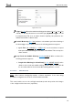
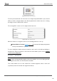
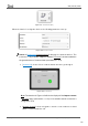
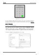
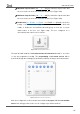
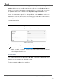
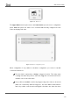
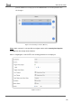
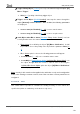
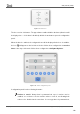
Table Of Contents
- Contents
- Document updates
- 1 Introduction
- 2 Configuration
- 2.1 General
- 2.2 Display
- 2.3 Inputs
- 2.4 Thermostat n
- ANNEX I. Video Intercom Operation
- ANNEX II. Internal Call Operation
- ANNEX III. Remote Control via IP
- ANNEX IV. Graphs
- ANNEX V. Differences with Z50 / Z100
- ANNEX VI. Communication Objects

Z50 / Z70 v2 / Z100
https://www.zennio.com Tecnical Support: https://support.zennio.com
111
Figure 100. Alarm
Trigger [0 / 1]: defines the value that will trigger the alarm (“0” or “1”; it is “1” by
default), i.e., the value that, when received through “[Ci] Alarm Trigger”, should
be interpreted by Z70 v2 as an alarm situation. Implicitly, this parameter also
defines the inverse “no alarm” value.
Periodic Monitoring [No / Yes]: activates or deactivates periodic monitoring of
the alarm trigger object. When activated, the following parameter appears:
➢ Cycle Time [30…65535][s] [
1…255][min/h]: sets the maximum accepted
time space without receiving the “no alarm” value before Z70 v2 adopts the
alarm situation.
Stop Visual and Audible Warning [disabled/enabled]: When activated, the
following parameter appears:
➢ Length of the Warning (0 = Silent Alarm) [0…
30…65535][s/min/h]: set the
duration of the visual and audible warning. After this time the alarm will still
be unconfirmed but the visual and audible warning will have ceased.
2.2.2.1.5.5 Video Intercom
Note: Video Intercom functionality requires a license installation. If not, even being
possible to configure it from ETS, its use will not be accessible.
This control enables access to the call log (bottom button) and to the preview of the images
of the configured video intercoms (top button).