
User Guide

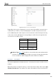
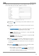
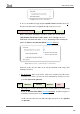
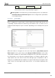
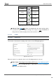
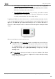
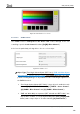
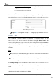
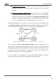
Table Of Contents
- Contents
- Document updates
- 1 Introduction
- 2 Configuration
- 2.1 General
- 2.2 Display
- 2.3 Inputs
- 2.4 Thermostat n
- ANNEX I. Video Intercom Operation
- ANNEX II. Internal Call Operation
- ANNEX III. Remote Control via IP
- ANNEX IV. Graphs
- ANNEX V. Differences with Z50 / Z100
- ANNEX VI. Communication Objects

Z50 / Z70 v2 / Z100
https://www.zennio.com Tecnical Support: https://support.zennio.com
102
Figure 89 Climate Control - Extended Mode.
Depending on the mode selected by the user, the control object will be sent to the bus a
certain value (see Table 7). The box will display the icon that corresponds to the new
mode. Additionally, if the status object receives from the bus a value that represents any
of the modes, the box will adopt the corresponding icon, while if an unrecognised value
is received, no icon will be shown.
Mode
Value sent
Auto
0 (0x00)
Heat
1 (0x01)
Cool
3 (0x03)
Fan
9 (0x09)
Dry
14 (0x0E)
Table 7. HVAC Mode vs. Object Value
Indicator Type [Icon / Text]: enables to select whether the status indicator which
each value is represented will be text type or icon type. As many drop-down lists
of icons or text boxes will be displayed as modes have been enabled.
2.2.2.1.4.3 Fan Control
This function implements a 2-button (increase / decrease) fan control, as well as an icon
indicator.
When this function is assigned to the box, a control object and a 1-byte status object (“[Ci]
(Climate) Fan Indicator”) are enabled. The status object (which needs to be linked to the