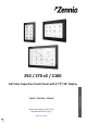
Z50 / Z70 v2 / Z100 ZVIZ50 / ZVIZ70V2 / ZVIZ100 Application Program Version: [3.6] User Manual Version: [3.6]_a www.zennio.
Z50 / Z70 v2 / Z100 CONTENTS Contents ........................................................................................................................................ 2 Document updates ........................................................................................................................ 5 1 Introduction .......................................................................................................................... 7 1.1 Z50 / Z70 v2 / Z100 ............................
Z50 / Z70 v2 / Z100 2.1.13.2 2.1.13.2.1 Internal Call (License required) ................................................................ 53 Contact n .............................................................................................................. 55 2.1.14 Avanced .................................................................................................................... 56 2.1.14.1 Cleaning Function ..................................................................................
Z50 / Z70 v2 / Z100 2.2.2.1.3.4 Numerical Controls ....................................................................................... 92 2.2.2.1.3.5 Enumeration.................................................................................................. 93 2.2.2.1.3.6 Two Scene ..................................................................................................... 94 2.2.2.1.3.7 Shutter ...........................................................................................
Z50 / Z70 v2 / Z100 DOCUMENT UPDATES Version Changes Page(s) Changes in the application program: [3.6]_a • - New devices: Z50 y Z100 Changes in the application program: [3.5]_a • New control: timer. • Graphs functionality is added. • RGBW control with independent objects. - Changes in the application program: [3.4]_a • • New control: Macros. • Rename of the control Timer to Scheduler. • Optimisation of Temp probe module.
Z50 / Z70 v2 / Z100 • Automatic Page Shaping • The "title" field of the controls is added to the prefix of their communication objects. • New 4-bytes numerical indicators and text indicator. • Chronothermostat. Changes in the application program: [3.0]_a • Date/time synchronisation via NTP • Remote control of the device https://www.zennio.com - Tecnical Support: https://support.zennio.
Z50 / Z70 v2 / Z100 1 INTRODUCTION 1.1 Z50 / Z70 V2 / Z100 Z50, Z70 v2 and Z100 are the easily and intuitively controllable high-performance colour touch screens from Zennio. The built-in features and functions make them the ideal solution for integral room control in hotels, offices or any other environments where controlling climate systems, lighting systems, shutters, scenes, etc. is required.
Z50 / Z70 v2 / Z100 Built-in temperature sensor Ambient luminosity sensor for brightness automatic adjustment. Proximity sensor for quick start. Buzzer for an audible acknowledgement of user actions (with the possibility of disabling it either by parameter or by object). Possibility of locking / unlocking the touch panel through binary orders or scenes, and setting a timed/automatic locking of the device (cleaning function). Pop-ups and Welcome Back object (binary or scene).
Z50 / Z70 v2 / Z100 This manual is focused on the features of Z70 v2, most of which are shared with the Z50 and Z100. ANNEX V. DIFFERENCES WITH Z50 / Z100 lists the main differences between them. https://www.zennio.com Tecnical Support: https://support.zennio.
Z50 / Z70 v2 / Z100 1.2 FUNCTIONALITY Screens application program feature the following functions: 12 General-Purpose Pages, with up to 12 Fully-Customisable Boxes each, which the integrator may configure as indicators or controls. ➢ Indicators: o Binary. o Float. o Enumeration. o Temperature. o Integer. o Cost. o Percentage. o Text. ➢ 1-Button Controls: o Switch. o Scene. o Two Object (Short Press/Long Press). o Constant (Counter / Scaling / Float). o Hold & Release. o Room State.
Z50 / Z70 v2 / Z100 1 Configuration Page (optional), which contains the time/date settings, the calibration of the built-in temperature probe, and the brightness and doorbell volume and tone adjustment, among others. 1.3 INSTALLATION shows the connection outline of Z70 v2 (For Z50 and Z100, please refer to the ANNEX V. DIFFERENCES WITH Z50 / Z100): 1 1. Touch screen. 2. Luminosity and proximity sensor. 3. Inputs connector. 4. Power supply. 5. Prog./Test button. 6. Prog./Test LED. 7.
Z50 / Z70 v2 / Z100 2 1. Touch screen. 2. Luminosity and proximity sensor. 3. Inputs connector. 4. Power supply. 5. Prog./Test button. 6. Prog./Test LED. 7. KNX connector. 8. Micro-USB connector. 9. Ethernet connector. 11 1 10 10. Temperature probe. 11. 12 Loudspeakers. 4 12. Microphone. 9 5 8 3 6 7 Figure 2 Schematic diagram (Z50) 1 1. Touch screen. 2. Luminosity and proximity sensor. 3. Inputs connector. 4. Power supply. 5. Prog./Test button. 6. Prog./Test LED. 7.
Z50 / Z70 v2 / Z100 to avoid interference to the KNX bus. This external power must be supplied to the device through the corresponding terminal (4) provided within the original packaging. Note: although the device will not turn functional until it is powered with the external supply, the KNX bus power should be enough to perform downloads from ETS (application program, group addresses, etc.). A short press on the Prog./Test button (5) will make the device enter the programming mode. The Prog.
Z50 / Z70 v2 / Z100 1.4 START-UP 1.4.1 EULA After the first start-up of the device, a dialog with the text EULA (End User License Agreement) will be displayed. The legal conditions of use described in EULA must be accepted by the end user before using the screen, so during the installation must be postponed. Once postponed, the EULA dialog will be displayed again after two hours or after a power failure. As long as the EULA is not accepted or postponed, screen navigation is not allowed.
Z50 / Z70 v2 / Z100 2 CONFIGURATION After importing the corresponding database in ETS and adding the device into the topology of the desired project, the configuration process begins by entering the Parameters tab of the device. 2.1 GENERAL This tab is divided into multiple screens, all of which contain a set of global parameters regarding the general functionality of the device, and therefore not specifically related to a particular page of the user interface. 2.1.
Z50 / Z70 v2 / Z100 The following parameters are shown: Inputs [disabled/enabled]1: enables or disables the “Inputs” tab in the tree on the left, depending on whether the device will or will not be connected any external accessories. For more information, see section 2.3. Thermostats [disabled/enabled]: enables or disables the “Thermostat” tab in the tree on the left. For more information, see section 2.4.
Z50 / Z70 v2 / Z100 Show Time [disabled/enabled]: permits setting whether the current time is displayed in the upper-left corner of any page or not. Important: the time will not be displayed on the top bar until both a time and a valid date have been set. Show Temperature [No / Internal Temperature Probe/ External Value]: sets whether the current temperature should show or not in the upper right corner of every page.
Z50 / Z70 v2 / Z100 bus. These requests will be made after updating the firmware or after power failure. Update Objects: enables the sending of read requests to update status objects and indicators. There are four options available, some of them with a configurable delay: ➢ [Disabled]: no read request, therefore objects are not updated.
Z50 / Z70 v2 / Z100 Time to Consider Inactivity: time that must elapse since the last press and/or proximity detection to consider inactivity state. Then the display backlight will dim. See section 2.1.3. ➢ With internal probe enabled: [[30…65535] [s] / [1…65535] [min/h]] ➢ With internal probe disabled: [[30…600] [s] / [1…10] [min]] Schedulers [disabled/enabled]: enables schedulers functionality. When enabled, a new tab is added in the tree on the left. See section 2.1.
Z50 / Z70 v2 / Z100 ➢ Allow Password Reset [disabled/enabled]: enables the password for accessing the Web server to be set to the factory default. Please refer to the user manual “Webserver Tools” (available in the Z70 v2 product section at the Zennio homepage, www.zennio.com) for detailed information about its functionality and the configuration.
Z50 / Z70 v2 / Z100 “[General] Activity”: 1-bit object to force activity/inactivity state on the device. For further information, please refer to the user manual “Proximity and Luminosity Sensor” and “Brightness” (available in the Z70 v2 product section at the Zennio homepage, www.zennio.com). “[General] Localization – Select” and “[General] Translations – Select”: 4-byte and 2-bytes objects to change, respectively, the locale and the language in the screen (see section 2.1.2).
Z50 / Z70 v2 / Z100 Use of a point (.) or a comma (,) for decimal separation (except in temperature that will always be shown with a point as separator). Position of the currency symbol in cost indicators. Language of all the texts shown on the screen. Example 1: Locale: es-ES → Language: Spanish – Region: Spain. Figure 7. Locale es-ES Example 2: Locale: en-US → Language: English – Region: USA. Figure 8.
Z50 / Z70 v2 / Z100 ETS PARAMETERISATION Figure 9. Locale Main Locale [enabled]: read-only parameter to make it evident that the main locale is always enabled. ➢ Select Locale: list of the available locales. Locale X [disabled/enabled]: enables the additional locale X. ➢ Select Locale: list of the available locales. The language and locale are changed via the following communication objects: 1-byte object “[General] Localization - Select”.
Z50 / Z70 v2 / Z100 region associated with that language will be set (and the language file 'text_language-ZZ.xlf', if it exists). 2-bytes object "[General] Translations - Select". To change the Language without affecting the region. ➢ The values expected by this object are the language code corresponding to ISO 639-1. ➢ When a valid language code is received, the texts from the 'text_languageZZ.xlf' file will be loaded.
Z50 / Z70 v2 / Z100 changing the scale of the temperatures. By receiving one ‘0’ through this object, the scale will switch to Celsius, while after receiving one ‘1’ it will switch to Fahrenheit. The selected scale applies to any temperatures shown on the screen and takes precedence over the scale corresponding to the locale. 2.1.3 BACKLIGHT Z70 v2 enables managing the brightness of the display according to two operating modes: normal mode and night mode.
Z50 / Z70 v2 / Z100 Figure 10. Security pop-up In case of setting up two levels, the first one is assumed to be enclosed by the second one. This means that whenever the device asks the user to type password #1 (to enter a certain item); password #2 will also be accepted. On the contrary, password #1 cannot be used instead of password #2. This behaviour permits, therefore, making password #2 available to users with further privileges while password #1 is assigned to users with fewer privileges.
Z50 / Z70 v2 / Z100 Security Levels [One Level / Two Levels]: parameter for selecting whether one or two security levels will be available. Note: with independence of the option selected here, it will be necessary to establish the security level desired for each specific page of controls. Protect Again after Home Button is Pressed [disabled/enabled]: if enabled, the security of the boxes and/or pages will be restored when the Home Button is pressed.
Z50 / Z70 v2 / Z100 ➢ Password 2 [Enter Password 2]: message shown when the user is required to type in the password for level 2. ➢ Error [ERROR]: message shown to the user when the typed password is not valid. ➢ New Password [New Password]: message shown to ask the user for a new password, during the password change process. ➢ Repeat Password [Repeat Password]: message shown when the user is required to re-type the new password.
Z50 / Z70 v2 / Z100 Other Controls: ➢ RGB Control. ➢ Macro. ➢ RGBW Control. To adjust the scheduler configuration settings, access the configuration panel from any of the boxes that have been parameterised as "scheduler" type (see section 2.2.2.1.5.8). From this panel navigation to the rest of the available schedulers will be possible, each of them represented by its corresponding icon configured from ETS. 3 2 4 7 8 5 6 1 Figure 13.
Z50 / Z70 v2 / Z100 6 Button to add a new action at the end of the list. 7 Checkbox to deactivate an action individually without deleting it. Timed action which will show the time of execution, the page where the 8 control is located, the control to be timed and the value to be sent once the configured time has been reached. The configuration of actions is done by entering edit mode. This happens when a new action is added or when clicking on one of the panel visible actions.
Z50 / Z70 v2 / Z100 ETS PARAMETERISATION After enabling Schedulers from “Configuration” screen (see section 2.1.1), a new tab will be incorporated into the tree on the left. Figure 15. Schedulers tab Title: text displayed at the top of the general scheduler panel. Number of Fixed Schedulers [1…30]: sets the number of schedulers available for setting on the display. ➢ Fixed Scheduler n Icon [Clock]: selects the icon to be displayed in the navigation area for each scheduler. 2.1.
Z50 / Z70 v2 / Z100 Figure 16. Screensaver There will also be an option to show an image on the screensaver. This image will be loaded from the webserver. Note: Please refer to the user manual “Webserver Tools” (available in the Z70 v2 product section at the Zennio homepage, www.zennio.com) for detailed information about its functionality and the configuration. The screensaver disappears when activity is triggered (either by a pulsation, proximity detection or any other event that triggers activity).
Z50 / Z70 v2 / Z100 ETS PARAMETERISATION After enabling Screensaver from “Configuration” screen (see section 2.1.1), a new tab will be incorporated into the tree on the left. Figure 17. Screensaver Tab Image [disabled]: parameter to show an image in the screensaver. For this functionality to be available, the Enable Web Configuration parameter must be active (see section 2.1.1).
Z50 / Z70 v2 / Z100 Note: To ensure correct measurement of the temperature probe, when the temperature probe is enabled, the display will be permanently switched on. 2.1.8 AMBIENT LUMINOSITY SENSOR Z70 v2 includes a sensor to measure the ambient luminosity level, so that the brightness of the display can be adjusted according to the current luminosity of the room. Please refer to the specific manual “Luminosity and Proximity Sensor” (available in the Z70 v2 product section at the Zennio homepage, www.
Z50 / Z70 v2 / Z100 Figure 19. Touch Locking. 1-Bit Object [enabled]: enables the 1-bit object “[General] Touch Locking” to trigger the touch lock. ➢ Value [0 = Unlock, 1 = Lock / 0 = Lock, 1 = Unlock]: parameter to select which value should trigger which action when received through the indicated object. Scene Object [disabled/enabled]: enables the touch locking and unlocking when receiving the configured scene value through the object (“[General] Scene: receive”).
Z50 / Z70 v2 / Z100 Doorbell: sharp and longer beep than the previous one, high intensity. The volume and ringtone of the doorbell can be chosen by parameter, object or from the screen itself. Enabling and disabling of this function can only be done by parameter. If enabled, the volume of the press and sending confirmation sounds will be possible to define. ETS PARAMETERISATION After enabling the “Custom” configuration of Sounds from “Configuration” screen (see section 2.1.
Z50 / Z70 v2 / Z100 ➢ Default Ringtone (after Programming) [Ringtone 1 / … / Ringtone 7]: desired melody for doorbell after ETS download. ➢ Default Volume (after Programming) [No sound / 1 / 2 / 3 / 4 / 5]: volume of the doorbell sound after ETS download. 2.1.11 UPDATE SETTING The Z70 v2 enables updates via USB of some of the available functions. These functionalities and how they should be updated are described in the following sections. ETS PARAMETERISATION Figure 21.
Z50 / Z70 v2 / Z100 2.1.11.1 FIRMWARE UPDATE For detailed information about the update process, please refer to the “Firmware update” specific document, available at www.zennio.com Note: Firmware updates do not re-set the alarm and error logs, nor does it clear the onscreen user configuration. Important: firmware updates via USB can be disabled in parameters (see section 2.1.11).
Z50 / Z70 v2 / Z100 When Z70 v2 recognizes the inserted USB flash drive, a USB icon will appear on the top bar and an informative dialogue will appear on the screen. The actions notified in the message will be, for each of the files with extension .lic detected: License Updated: a new license has been installed. Invalid license found: a .lic file has been detected but the information it contains is not valid.
Z50 / Z70 v2 / Z100 For example, “text_en-GB.xlf” would be the language corresponding to English and United Kingdom locale. A generic translation file can also be generated for a language that is not associated with a particular locale. To do this, it is necessary to follow the nomenclature “text_language-ZZ.xlf”.
Z50 / Z70 v2 / Z100 2.1.11.4 CUSTOM ICONS Z70 v2 enables to import customised icons. These icons are parameterised from ETS and will appear with the name “Cx” (see sections 2.2.1.3 and 2.2.2.1). In order to display them correctly on the screen, importing all these icons using a USB with FAT32 format is necessary.
Z50 / Z70 v2 / Z100 Link: icons for direct link boxes or pages (maximum 40 customised icons). Status: icons for box indicators (maximum 40 customised icons). Notes: ➢ The maximum size of the icons cannot exceed 20KB. ➢ If the name or the format of any of the files is not correct, it will not be imported.
Z50 / Z70 v2 / Z100 Figure 24. Configuration to export icon in Illustrator. 2.1.12 IP CONFIGURATION Z70 v2 is able to communicate with other external (GetFace IP) or internal (Z41 COM o Z70 v2) units via Ethernet connection. Such communications will require correct configuration of certain general IP parameters. ETS PARAMETERISATION Figure 25. IP Configuration Device Description: assigns a name to the device.
Z50 / Z70 v2 / Z100 be indicated to access Webserver Tools, on the outdoor unit (GetFace IP) or on a contact of another display to make an internal call. Note: it is recommended to set this IP address out of the range of addresses assigned by the home router to prevent possible conflicts with the IP address visible to the internet. ➢ Subnet Mask [255.255.255.0]: must match the mask of the network to which Z70 v2. ➢ Specify Gateway [disabled/enabled]: when enabled permits introduce a gateway [192.168.1.1].
Z50 / Z70 v2 / Z100 • IP Address [192.168.1.100]. • Subnet Mask [255.255.255.255.0]. • Specify Gateway [Disabled/Enabled]: Enabling this allows you to enter a gateway [192.168.1.1]. This only needs to be enabled if the Z70 v2 is on a different network to the other units it is communicating with.
Z50 / Z70 v2 / Z100 2.1.13 VOIP CALLS (LICENSE REQUIRED) Note: VoIP calls functionality requires a license installation. If not, even being possible to configure it from ETS, its use will not be accessible Z70 v2 is capable of receiving, over its Ethernet connection, voice and video calls from: A Zennio indoor unit: Z41 COM or Z70 v2. These calls are referred in this document as internal calls. A Zennio outdoor unit: GetFace IP. These calls are referred in this document as video intercom calls.
Z50 / Z70 v2 / Z100 Internal Calls [disabled/enabled]: enables or disables “Internal Call” tab for the configuration of internal calls to other devices (Z41 COM or Z70 v2). See section 2.1.13.2 for more details. If any of the above parameters are enabled, the following will appear: Default Ring Volume (after Programming) [No sound / 1 / 2 / 3 / 4 / 5]: define the VoIP calls volume after Programming.
Z50 / Z70 v2 / Z100 2.1.13.1 VIDEO INTERCOM (LICENSE REQUIRED) Note: Video Intercom functionality requires a license installation. If not, even being possible to configure it from ETS, its use will not be accessible. Z70 v2 will be able to receive calls and show images from the camera of a Zennio outdoor unit, GetFace IP. Moreover, the door can be opened and a common call log is available for all configured video intercom.
Z50 / Z70 v2 / Z100 ETS PARAMETERISATION After enabling Video Intercom in the “VoIP Calls” screen (section 2.1.13), a new tab will be incorporated into the tree on the left. Figure 29. Video intercom “Call Accepted” Label [CALL ACCEPTED]: text to be displayed when the call is accepted on a synchronised device. “Call Rejected” Label [CALL REJECTED]: text to be displayed when the call is rejected on a synchronised device.
Z50 / Z70 v2 / Z100 2.1.13.1.1 Outdoor Unit n The video intercom used can be of two types: private or community. The main difference between them is that community video intercom does not enable the camera image to be viewed if there is no incoming or ongoing call. In case the unit does not have a camera, the images will not be viewed in case of any event, no matter what type of video door phone it is.
Z50 / Z70 v2 / Z100 Unit with Camera [disabled / enabled]: define whether the installed video intercom has camera. Outdoor Unit ID [ID_n]: alphanumerical identifier of GetFace IP (field Phone Number (ID), in Services → Phone). Note: the characters included in this field must comply RFC 2396 standard. Set Static IP [disabled / enabled]. If Z70 v2 and GetFace IP are in different networks, IP Address [192.168.1.
Z50 / Z70 v2 / Z100 the KNX object. Choosing the Object Value [1 = Open / 0 = Open] that will open the door is possible. Important: For safety reasons, it is recommended not to use this communication object or to use it under the responsibility of the integrator. Door n [disabled/enabled]: enables or disables every door, up to 4 for each outdoor unit. Note: the door concept in Z70 v2 refers to the switches configured in GetFace IP in section Hardware → Switches.
Z50 / Z70 v2 / Z100 Figure 31. Generic Outdoor Unit This tab is analogous to "Outdoor unit n", but the video intercom identification fields (Outdoor unit ID and Set Static IP) are excluded. For more information on the configuration of the parameters see section 2.1.13.1.1. 2.1.13.2 INTERNAL CALL (LICENSE REQUIRED) Note: Internal Call functionality requires a license installation. If not, even being possible to configure it from ETS, its use will not be accessible.
Z50 / Z70 v2 / Z100 ETS PARAMETERISATION After enabling Internal Calls, in “VoIP Calls” tab (section 2.1.13), a new tab will be incorporated into the tab tree: Figure 32. “Internal call” tab Page Title: Incoming / Outgoing / Ongoing Call: titles of the different dialogues of the internal calls. “Communication Error” / “End Call” / “Busy Contact” Label: text displayed on screen when a call cannot be established with the contact, the call is terminated or the contact has an ongoing call, respectively.
Z50 / Z70 v2 / Z100 Note: For further information about the configuration and importation of contacts via web, please refer to the “Webserver Tools” manual (available in the product section of Z70 v2 in Zennio web portal, www.zennio.com). 2.1.13.2.1 Contact n ETS will enable to configure a list of up to 8 contacts for each Z70 v2. For Z70 v2 to be able to make calls to other screens (Z41 COM or Z70 v2), certain data, such as the ID and IP address of each contact, will need to be correctly configured.
Z50 / Z70 v2 / Z100 2.1.14 AVANCED Independent tab for the parameterisation of some advanced functions. These functions are explained next. ETS PARAMETERISATION After enabling the Advanced Configuration from “Configuration” screen (see section 2.1.1), a new tab will be incorporated into the tree on the left. Figure 34. Advanced Configuration. Cleaning Function [disabled/enabled]: enables or disables the “Cleaning Function” tab. See section 2.1.14.1 for details.
Z50 / Z70 v2 / Z100 Figure 35. Cleaning Function Message ETS PARAMETERISATION After enabling Cleaning Function from “Advanced” screen (see section 2.1.14), a new tab will be incorporated into the tree on the left. Figure 36. Cleaning Function. Time to Exit Cleaning Status [5...15…65535][s] [1…65535][min/h]: timeout to deactivate the cleaning function after triggered. Message Notification [Cleaning…]: textbox to enter the desired message.
Z50 / Z70 v2 / Z100 2.1.14.2 POP-UPS This function permits showing the user a pop-up message of up to four lines of text on the display, each of which can be object-dependant or set in parameters. It is possible to enable up to 6 pop-ups, each of which can be launched in 3 different ways: by using a 1-bit object, by using a 1-byte object or by modifying the text of one of the messages. They can also be launched when activating the different states of the control of Room State (see section 2.2.2.1.2.6).
Z50 / Z70 v2 / Z100 Pop-Up n [disabled/enabled]: allows to enable/disable each pop-up. After enabling each pop-up, a new tab will be incorporated into the tree on the left named “Pop-Up n”. 2.1.14.2.1 Pop-Up n Figure 39. Pop-Up n Pop-Up Trigger: sets the type of object that is used to show the pop-up message. ➢ [1 Bit Object]: when this option is selected, the object “[General][Pop-Up n] 1 Bit” appears to launch the pop-up message.
Z50 / Z70 v2 / Z100 ➢ [Changes in 14 Bytes Objects]: when this option is selected, the pop-up will appear on the screen when a value is received through the objects “[General][Pop-Up n] Line x”. Line [1,4] [Fixed Text / Text Received from Object]: sets whether the corresponding text line will be pre-defined or object-dependent. If “Fixed Text” is selected, the following parameter will appear ➢ Text: textbox to enter the desired text for the corresponding line.
Z50 / Z70 v2 / Z100 Time to Activate the Welcome Object [30...65535][s] [1…65535][min/h] : sets the minimum time that should elapse after the last button touch (or presence detection, when the proximity sensor is enabled) before the next one triggers the execution of the welcome back function. Send Object Trigger [Press Button / Detect Presence]: sets whether the welcome back object is sending after a touch in the screen or when the proximity sensor detects presence.
Z50 / Z70 v2 / Z100 2.2 DISPLAY 2.2.1 PAGES The user interface is organised into pages (up to twelve different pages, in addition to the ‘Configuration Page’), each of which can be accessed from the Menu page, which (unless the contrary has been parameterised) is automatically shown after the start-up. The twelve pages are general purpose, at the entire disposal of the integrator, who may include up to twelve controls with different functionalities per page.
Z50 / Z70 v2 / Z100 ETS PARAMETERISATION Figure 43. General pages configuration The parameters available are: Number of Pages [1…12]: number of general purpose pages that will be activated on the device. For each page a dedicated ETS tab will be shown for configuration. Default Page [Menu]: dropdown list that sets the page that will behave as the default page. This page will be the one shown after the inactivity time elapsed.
Z50 / Z70 v2 / Z100 2.2.1.1 MENU The user interface may have up to twelve pages of general purpose, each of which can host up to twelve different controls or indicators. Figure 44. Menu Page ETS PARAMETERISATION The Menu tab allows defining generic options regarding the enabled control pages, which can be accessed from this screen. Figure 45. Menu. The parameters available are: Title: text field that identifies the menu pages.
Z50 / Z70 v2 / Z100 ➢ Use this Text in the Device [disabled/enabled]: enables the text to be used as the page title in the device. Automatic Page Shaping [disabled/enabled]: enables choosing whether the pages in Menu should be automatically distributed depending on the number of pages configured, or be displayed as a static 3x4 grid. 2.2.1.
Z50 / Z70 v2 / Z100 Figure 47. Configuration tab https://www.zennio.com Tecnical Support: https://support.zennio.
Z50 / Z70 v2 / Z100 Title: text field that identifies the configuration page. In addition, this field allows changing the name of the tab in ETS left menu, as shown in the Figure 47. ➢ Use this Text in the Device [disabled/enabled]: allows the text to be used as the page title in the device. Automatic Page Shaping [No / Yes]: allows choosing whether the boxes in the Configuration Page should be automatically distributed depending on the number of boxes configured, or be displayed as a static 3x4 grid.
Z50 / Z70 v2 / Z100 • [No / Yes]: sets whether the page is password-protected at level 1 or without a password. ➢ Two Levels: • [No / Level 1 / Level 2]: sets the level of security to access the configuration page. Time/Date [disabled/enabled]: if enabled, the date and time of the device can be set directly from the user interface: Figure 48. Time and date. Device [disabled/enabled]: enables or disables the “Device” tab in the left menu. For more information, see section 2.2.1.2.
Z50 / Z70 v2 / Z100 Alarm confirmed, but not finished Alarm finished and confirmed Table 2. Alarm Log Icons This centralised file may be useful when the user needs to check the status of a set of alarm controls distributed across several pages. Figure 49. Alarm Log To delete the record, press and hold the button , at the bottom right of the window for more than 3 seconds. Note: For information on alarms, see section 2.2.2.1.5.4.
Z50 / Z70 v2 / Z100 Note: the voice control and device pairing boxes will always be visible when the Remote Control parameter is enabled and hidden when the Remote Control parameter is disabled. Moreover, for all these controls, the following parameters can be configured: Label: text that will appear to identify the box. Protect [No / Yes] / [No / Level 1 / Level 2]: exactly the same as the page protection explained above, but for the boxes.
Z50 / Z70 v2 / Z100 Figure 51. Configuration Page. Device. Programming Button [disabled/enabled]: control/indicator that shows the status of the Prog./Test LED of the device. In particular, it permits entering/leaving the programming mode as by pressing the actual programming button of the device.
Z50 / Z70 v2 / Z100 Label: text that will appear to identify the box. 2.2.1.2.2 Profile Z70 v2 configuration page, if Device is enabled, will display a button to access the visual and sound settings of the device: Figure 52. Profile ETS PARAMETERISATION After enabling the Profile from “Configuration Page” screen (see section 2.2.1.2), a new tab will be incorporated into the tree on the left. Figure 53. Configuration Page. Profile.
Z50 / Z70 v2 / Z100 Theme [disabled/enabled]: enables or disables the box for the selection of the theme. Volume [disabled/enabled]: box to control the volume of pulsation and sending sound. There are three volume levels in addition to the mute option. Doorbell Volume [disabled/enabled]: box to control the volume of doorbell. There are five volume levels in addition to the mute option.
Z50 / Z70 v2 / Z100 Figure 55. Configuration page - VoIP calls Video Intercom Ringtone [disabled/enabled]: box to change the melody to be played when receiving a call from an external unit. Internal Call Ringtone [disabled/enabled]: box to change the melody to be played when receiving a call for an internal unit. Ringtone Volume [disabled/enabled]: enables the box to modify the calls tone volume.
Z50 / Z70 v2 / Z100 When enabling the mode, the value ‘1’ is sent through the object “[VoIP] “Do Not Disturb” Mode” and when the timing expires it is sent the value ‘0’. It is also possible to stop the countdown disabling the mode (by manually or through the communication object). 2.2.1.3 PAGE N Z70 v2 has up to twelve general purpose pages that can be enabled from the "Pages" tab. Thus, a new tab called Page n will be displayed for each of the n enabled pages.
Z50 / Z70 v2 / Z100 ETS PARAMETERISATION Figure 58. Configuration Page n This screen contains the following parameters: Title: text field that identifies each of the enabled pages. In addition, this field allows changing the name of the tab in ETS left menu, as shown in the Figure 58. ➢ Use this Text in the Device [disabled/enabled]: allows the text to be used as the page title in the device. Icon [Kitchen]: sets the icon that will represent the page in the Menu page.
Z50 / Z70 v2 / Z100 Control Distribution [Nothing / Control 1…Control 180]: enables selecting which control, from a list of 180 controls, will be placed in each of the twelve possible boxes on the screen. Protect: sets whether the page will be password-protected or not. Depending on the security levels configured (one or two; see section 2.1.4) this list will contain the following options: ➢ One Level: • [No / Yes]: sets whether the page is password-protected at level 1 or without a password.
Z50 / Z70 v2 / Z100 Buttons Border [disabled/enabled]: sets whether the buttons will have an outline or if only the button icon is displayed. Touch Zone for 1-Button Controls: this parameter defines whether the touch zone for 1-button controls is the entire box or a separated button. The behavior in each case is: ➢ [Box]: actions will take place by clicking anywhere in the box. ➢ [Button]: a separate button will be displayed in the upper right of the box.
Z50 / Z70 v2 / Z100 Visualization: box format. The available box formats in Z70 v2 are: ➢ [Indicator]: the box will work as a status indicator. ➢ [1-Button Control]: the box will work as a one-button control. ➢ [2-Button Control]: the box will work not only as a status indicator, but also as a two-button control. ➢ [Climate Control]: the box will act as a climate indicator and a climate control. ➢ [Other]: the box will implement some other special functionality.
Z50 / Z70 v2 / Z100 Protect: sets whether the box will be password-protected or not. Depending on the security levels configured (one or two; see section 2.1.4) this list will contain the following options: ➢ One Level: • [No / Yes]: sets whether the control is password-protected at level 1 or without a password. ➢ Two Levels: • [No / Level 1 / Level 2]: sets the level of security to operate on the control. Note: neither indicators nor change-scale buttons can be protected. INDICATORS 2.2.2.1.
Z50 / Z70 v2 / Z100 Figure 63 Indicator - Enumeration Number of Value [1…2…6]: sets the number of states in the enumerated list. For every distinguished state, the parameter Value [0…255] will become available together with the corresponding indicator. Indicator Type [Icon / Text]: enables to select whether the status indicator which each value is represented will be text type or icon type.
Z50 / Z70 v2 / Z100 Signed -128 – 127 [Ci] 1-Byte Signed Int Indicator Unsigned 0 – 65535 [Ci] 2-Byte Unsigned Int Indicator Signed -32768 – 32767 [Ci] 2-Byte Signed Int Indicator Unsigned 0 – 4294967295 [Ci] 4-Byte Unsigned Int Indicator Signed -2147483648 – 2147483647 2 Bytes 4 Bytes Percentage 1 Byte 0 – 100 2 Bytes -671088.64 – 670433.
Z50 / Z70 v2 / Z100 2.2.2.1.1.4 Text The box will show the text received through the communication object “[Ci] Text Indicator”. Figure 66. Indicator - Text. 2.2.2.1.2 1-BUTTON CONTROL The box configured with this control type will have a button (at the top right or throughout the box, see section 2.2.2) and a state indicator. In addition, through Function parameter, it will be possible to select the specific function that the control will perform. Figure 67 1-Button Control (Box). 2.2.2.1.2.
Z50 / Z70 v2 / Z100 Figure 68. 1-Button Control - Switch Action [Send 0 / Send 1 / Toggle 0/1]: specifies what value will be sent to the bus after pressing the control button. Indicator Type [Icon / Text]: allows selecting whether the status represented by each indicator value will be text type or icon type. 2.2.2.1.2.
Z50 / Z70 v2 / Z100 Different objects are used to send values for short and long pulsations: "[Ci] Two objects - Short Press" and "[Ci] Two objects - Long Press", respectively. If the option chosen is “Send 0” or “Send 1”, the object "[Ci] Two objects Indicator" will appear for the box indicator, which is automatically updated after the control order is sent and when values are received from the bus.
Z50 / Z70 v2 / Z100 Figure 71. 1-Button Control - Scene Action [Run / Run and Save]: sets whether the device will only send scene execution orders (after a short press) or if it will be possible, to send scene save orders (after a long press). Scene Number [1…64]: scene value to be sent. Object to Use [General Scene Object / Individual Box Scene Object]: specifies whether the scene value will be sent through the object "[General] Scenes: Send" or through the individual object "[Ci] Scene: Send". 2.2.2.1.
Z50 / Z70 v2 / Z100 Table 4 shows the permitted value range and the name of the object through which the values are sent to the bus. Function Size Sign Range Related Object Unsigned [0…255] Signed [-128…0…127] Unsigned [0…65535] Signed [-32768…32767] [Ci] 1-Byte Unsigned Int Control 1 Byte [Ci] 1-Byte Signed Int Control Integer [Ci] 2-Byte Unsigned Int Control 2 Bytes Scaling 1 Byte Float 2 Bytes [0…100] [Ci] 2-Byte Signed Int Control [Ci] Percentage Control [-671088.64…0…670433.
Z50 / Z70 v2 / Z100 Show Pop-Up When Activating MUR [No / Pop-Up 1 / … / Pop-Up 6]: allows to select the pop-up to be displayed when the MUR mode is activated. Note: the pop-ups selected must be activated (see section 2.1.14.2). This control will have associated a dedicated object for the indicator (“[Ci] Room State Indicator”), which is automatically updated after the control order is sent and when values are received from the bus. 2.2.2.1.2.
Z50 / Z70 v2 / Z100 2-BUTTON CONTROL 2.2.2.1.3 The box configured with this control type will have a button at the right and a state indicator. In addition, through Function parameter, it will be possible to select the specific function that the control will perform. Figure 75 2-Button Control (Box) 2.2.2.1.3.
Z50 / Z70 v2 / Z100 2.2.2.1.3.2 Switch + Indicator In the same way the previous control, when pressing in any of the controls configured as switch, Z70 v2 will send the parameterised binary value to the bus through the object "[Ci] Switch". However, the indicator is independent and will only be updated according to the value received by the dedicated object. Figure 77.
Z50 / Z70 v2 / Z100 ➢ For percentage indicator, the symbol % always will be displayed as unit. ➢ The temperature indicator will be shown in ºC or ºF depending on the value of the active locale (see section 2.1.2). In addition, the following parameters will be available for this control type: • Button to Change between ºC and ºF [disabled/enabled]: enables a control that allows the temperature scale to be changed from the box itself: Figure 78.
Z50 / Z70 v2 / Z100 Long Press Threshold Time [4…6…50] [ds]: sets the minimum time the user should hold the button in order to consider it a long press. State Object [Short Press Object / Long Press Object]: allows setting the control command to which the status indicator, "[Ci] Two Objects - Indicator", will obey. This object can also receive values from the bus. Indicator Type [Icon / Text]: allows selecting whether the status indicator which each value is represented will be text type or icon type. 2.2.
Z50 / Z70 v2 / Z100 Function Size Sign Minimum Value Maximum Value Increment on short press Increment on long press Signed [-128…127] [-128…127] [1…127] [1…10…127] Unsigned [0…255] [0…255] [1…255] [1…10…255] Signed [-32768…32767] [-32768…32767] [1…32767] [1…32767] Unsigned [0…65535] [0…65535] [1…65535] [1…65535] 1 Byte Counter 2 Byte Scaling 1 Byte [0... 100] [0... 100] [1…100] [1...10…100] Float 2 Byte [-671088.64… …670433.28] [-671088.64… …670433.28] [0.1...0.
Z50 / Z70 v2 / Z100 Indicator Type [Icon / Text]: allows selecting whether the status indicator which each value is represented will be text type or icon type. As many drop-down lists of icons or text boxes will be displayed as states have been enabled in the previous parameter. 2.2.2.1.3.
Z50 / Z70 v2 / Z100 2.2.2.1.3.7 Shutter Shutter control permits sending move up and move down ("[Ci] Shutter - Move”) or stop (“[Ci] Shutter – Stop/Step”) to control a shutter actuator connected to the bus by pressing the buttons in the box. In addition, the box will contain an indicator that will permanently show, as a percentage, the value of the status object (“[Ci] Shutter Position”).
Z50 / Z70 v2 / Z100 2.2.2.1.3.8 Dimmer The light control function permits making use of the two buttons in the box to send orders to a light dimmer, either through a binary object or through a 4-bit object. Moreover, the box will permanently display the current value of the dimming status object (“[Ci] Light – Dimming Indicator”), which needs to be linked to the analogous object from the dimmer (as it does not get automatically updated on button presses). Figure 84.
Z50 / Z70 v2 / Z100 releasing it as soon as he gets the desired light level, therefore with no need of performing successive long presses for regulations greater than the parameterised step. Additionally, the dimmer control will have the 1-byte object "[Ci] Precise Dimming (Only Schedulers and Macros)" which will be used by schedulers and macros for a precise lighting control. 2.2.2.1.3.
Z50 / Z70 v2 / Z100 This control will have associated a dedicated object for the indicator (“[Ci] Room State Indicator”), which is automatically updated after the control order is sent and when values are received from the bus. 2.2.2.1.4 CLIMATE CONTROL This category covers a set of functions related to the climate control. The available options for Function (and for the dependent parameters) are as follows: 2.2.2.1.4.
Z50 / Z70 v2 / Z100 Figure 86 Climate Control – Temperature Setpoint The parameters available are: Button to Change between ºC and ºF [disabled/enabled]: enables a control that allows the temperature scale to be changed from the box itself: Include Plus Sign before Positive Numbers [disabled/enabled]: adds the ‘+’ sign before positive temperature values. Indicator Type: ➢ [Just Setpoint Temperature]: only the setpoint temperature will be displayed.
Z50 / Z70 v2 / Z100 Figure 87. Setpoint Temperature with different indicator types Minimum Value [-99…10…199]: minimum value than can be reached by the control after a number of presses on the bottom button. Maximum Value [-99…30…199]: maximum value than can be reached by the control after a number of presses on the top button. Increment on Short Press [0.1…0.5…10]: sets the increase or decrease step to be applied to the current value on every short press over the top or bottom buttons, respectively.
Z50 / Z70 v2 / Z100 activate the Cool mode. A centered indicator will reflect, as an icon, the currently active mode. Figure 88 Climate Control - Heat/Cool Mode When the user activates the Cool mode, the device will send the value “0” through the control object, while on the activation of the Heat mode the value “1” will be sent.
Z50 / Z70 v2 / Z100 Figure 89 Climate Control - Extended Mode. Depending on the mode selected by the user, the control object will be sent to the bus a certain value (see Table 7). The box will display the icon that corresponds to the new mode. Additionally, if the status object receives from the bus a value that represents any of the modes, the box will adopt the corresponding icon, while if an unrecognised value is received, no icon will be shown.
Z50 / Z70 v2 / Z100 status object of the fan actuator) will express, as a percentage, the value of the current fan level, which will be represented with a variable icon on the box. Figure 90 Climate Control - Fan Speed Levels [1…5]: sets how many speed levels will be available in the control. 1 to 5 levels. Control Type: sets the type of the communication objects that will control the fan level.
Z50 / Z70 v2 / Z100 Figure 91 Fan Control – Auto Mode. In case to be disabled (supposing that Speed Levels has been set to “3”), the fan levels that can be navigated through short presses are: Auto ( 0 ) Minimum Medium Maximum On the other hand, marking the checkbox enables the one-bit object “[Ci] (Climate) Fan Control - Auto mode”, which will trigger the Auto mode when it receives the value “1” or “0”, depending on the subsequent parameter Value to Set the Auto Mode [Send 0 / Send 1]).
Z50 / Z70 v2 / Z100 (0) Minimum Medium Maximum Here, the Auto mode is only activated by long press. Allow speed 0: sets whether the speed level 0 will be present or not. When the Auto Mode without a dedicated object has been configured, this option will be necessarily activated. 2.2.2.1.4.
Z50 / Z70 v2 / Z100 Special Mode Icon Object Value Comfort 1 (0x001) Standby 2 (0x002) Economy 3 (0x003) Protection 4 (0x004) Auto Mode 5 (0x005) Table 8. Special Modes vs. Icon vs. Object Value Indicator Type [Icon / Text]: allows selecting whether the status indicator which each value is represented will be text type or icon type. If “Text” is selected, as many text boxes will be displayed as modes have been enabled. 2.2.2.1.5 OTHER 2.2.2.1.5.
Z50 / Z70 v2 / Z100 ➢ “Three Single Colour Objects (DPT 5.001)”: three 1-byte objects (“[Ci] Red Channel”, “[Ci] Green Channel” and “[Ci] Blue Channel”) will be enabled, which can send orders and receive statuses. ➢ “One RGB Object (DPT 232.600)”: only one 3-byte object will be enabled (“[Ci] RGB Color”). The light levels of the three channels are sent (and received) concatenated into the above 3-byte object.
Z50 / Z70 v2 / Z100 Figure 96. RGB/RGBW Colour Palette 2.2.2.1.5.2 RGBW Control The RGBW control is analogous to the above RGB control, although it also lets controlling a specific fourth channel for white (“[Pn][Bi] White Channel”). It also has the particularity of being able to choose a colour object. Figure 97. RGBW Control Object Type [Four Single Colour Objects (DPT 5.001) / RGB and White Objects Separated (DPT 232.600 and DPT 5.001) / One RGBW Object (DPT 251.
Z50 / Z70 v2 / Z100 ➢ “One RGBW Object (DPT 251.600)”: a 6-bytes object will be enabled: “[Pn][Bi] RGBW Color” through which the light levels of the four channels are sent and received concatenated. 2.2.2.1.5.3 Page Direct Link This control allows a shortcut to the page indicated by parameter. To configure a box as a page direct link type control, the following parameter must be set in addition to the icon: Figure 98.
Z50 / Z70 v2 / Z100 Pressing the ‘Home’ button: it will silence the sound notification and end the flashing, but it will not confirm the alarm. The alarm box icon will continue blinking. Press the ‘OK’ button in the alarm box: this will silence the sound notification, end the flashing light, confirm the alarm, and cause the icon to stop blinking. When this button is pressed, the binary object "[Ci] Alarm Confirmation" with the value “1” will be sent through the bus.
Z50 / Z70 v2 / Z100 Figure 100. Alarm Trigger [0 / 1]: defines the value that will trigger the alarm (“0” or “1”; it is “1” by default), i.e., the value that, when received through “[Ci] Alarm Trigger”, should be interpreted by Z70 v2 as an alarm situation. Implicitly, this parameter also defines the inverse “no alarm” value. Periodic Monitoring [No / Yes]: activates or deactivates periodic monitoring of the alarm trigger object.
Z50 / Z70 v2 / Z100 Figure 101. Video intercom (Box) From the preview window, the video intercom configured by default will be opened and it will be possible to navigate between the different parameterised video intercoms, showing the image from the external unit's camera. The call log will be common to all configured video intercom. Figure 102.
Z50 / Z70 v2 / Z100 Figure 103. Internal Call (Box) When the function is assigned to the box, the following parameter come up: Figure 104. Internal call box Interface [Contact List / Numeric Keypad]: dialog type for internal calls box. This parameter is only available if Import contacts “from web” has been selected in the general screen of “Internal Calls” (see section 2.1.13.2). ➢ [Contact List]: shows a list of contacts and two arrows to go through it. Figure 105.
Z50 / Z70 v2 / Z100 Figure 106. Numeric Keypad. For more detailed information about the functions and controls of the different dialogues that appear in Z70 v2 in relation to internal calls functionalities, please refer to ANNEX II. Internal Call Operation. 2.2.2.1.5.
Z50 / Z70 v2 / Z100 Minimum Setpoint Value [-99 … 18 … 199][ºC]: minimum setpoint value that the user can be set on the chronothermostat panel (see Figure 109). Maximum Setpoint Value [-99 … 30 … 199][ºC]: maximum setpoint value that the user can be set on the chronothermostat panel (see Figure 109).
Z50 / Z70 v2 / Z100 For each of the six timed actions of each page it is necessary to select the days of the week on which the action should be performed, as well as the specific time of day (the first day of the week will depend on the parameterisation of screen Locale; see section 2.1.2). After that, the user should select the temperature setpoint that will be sent. Instead of a temperature setpoint, it is also possible to send a switch-off order to the thermostat.
Z50 / Z70 v2 / Z100 Figure 111. Macro box The upper button star/stop the macro and lower button open the macro configuration panel. Within this panel, the actions to be executed with the delay configured for each action are displayed in order. Figure 112. Macro configuration panel Macro configuration is very similar to schedulers configuration (see section 2.1.5) with some minor differences: The time field is replaced by a delay to trigger the action.
Z50 / Z70 v2 / Z100 placed, it will be necessary to press the validate button or close the panel to save the changes. Figure 113. Reordering of actions (Macros) Note: within a macro it is only possible to configure actions with a security level equal to or lower than the security level of the box. When configuring this control in ETS, the following parameters are displayed: Figure 114. Macro https://www.zennio.com Tecnical Support: https://support.zennio.
Z50 / Z70 v2 / Z100 Trigger: Binary Object [enabled]: runs/stops the macro through the object “[Ci] Macro: Trigger”. ➢ Value [0 / 1]: polarity of the binary trigger object. Trigger: Scene Object [disabled/enabled]: runs/stops the macro through the object “[General] Scenes: Receive”. When enabled, the following parameters are displayed: ➢ Scene to start (0 = Disabled) [0 … 64]: scene to run the macro. ➢ Scene to stop (0 = Disabled) [0 … 64]: scene to stop the macro.
Z50 / Z70 v2 / Z100 Figure 115. Timer box The box consists of 2 buttons. The upper button enables/disables the timer (all actions will be displayed as --:-- if the timer is disabled), while the lower button opens the configuration panel. When the timer is enabled, the configured hours will be displayed in the box. In addition, the icon will appear on the left side of the box if it has been configured as a one-shot timer or the days of the week if it has been configured as a daily/weekly timer.
Z50 / Z70 v2 / Z100 the action will always be shown with the parameterised text/icon. Within each action, the time to send every action is configured. Days of the week: set the days of the week on which sending will occur. Type of timer: ➢ Daily/Week timer : the configured actions will be sent on the selected days of the week without ever being disabled. ➢ One-shot timer : the actions will be sent when the configured time is reached. Once all actions have been sent, the timer is disabled.
Z50 / Z70 v2 / Z100 ➢ Scene Number [1 … 64]: scene sent when configured time is reached. ➢ Scene Object [General Scene Object / Individual Box Scene Object]: sets the object through which the scene is sent. In case of choosing the Individual Box Scene Object option the object "[Ci] Timer – Send Scene Control" will be displayed. Indicator Type [Icon / Text]: sets whether the indicator displayed within the action is an icon or text.
Z50 / Z70 v2 / Z100 2.3 INPUTS Z70 v2 incorporates four analogue/digital inputs, each configurable as a: Binary Input, for the connection of a push button or a switch/sensor. Temperature Probe, for the connection of a temperature sensor from Zennio. Motion Detector, for the connection of a motion detector from Zennio. 2.3.1 BINARY INPUT Please refer to the specific user manual “Binary Inputs”, available in the Z70 v2 product section, at the Zennio website (www.zennio.com). 2.3.
Z50 / Z70 v2 / Z100 2.4 THERMOSTAT N Z70 v2 implements two Zennio thermostats which can be enabled and fully customised. Please refer to the specific manual “Zennio Thermostat” (available in the Z70 v2 product section at the Zennio website, www.zennio.com) for detailed information about the functionality and the configuration of the related parameters. https://www.zennio.com Tecnical Support: https://support.zennio.
Z50 / Z70 v2 / Z100 ANNEX I. VIDEO INTERCOM OPERATION INCOMING CALL When Z70 v2 receives a call from a video door phone, the user interface in Figure 118 will be displayed. Figure 118. Incoming call During an incoming call, besides displaying the camera image, the following functions will be available: Accept Call: opens the ongoing call dialog (Figure 121) and notifies others synchronized screens in the same network that the call has been accepted: Figure 119.
Z50 / Z70 v2 / Z100 The GetFace IP does not manifest the call rejected, so the call continues from the point of view of the visitor. Open Door: sends the door opening order via an HTTP command and, as configured in sections 2.1.13.1.1 and 2.1.13.1.2, a communication object. Besides all other synchronized screens will be notified that the call has been answered, although the call will remain in progress. Note: Configuring automatic door opening when receiving a call is possible (see section 2.1.13.1.1 and 2.
Z50 / Z70 v2 / Z100 Speakers Volume: up to 5 levels of volume available plus level 0 or mute. The selected value is saved to apply in future calls. Mute Microphone: toggles between mute and enable the microphone. Exit: equivalent to reject call button. PREVIEWING IMAGES FROM THE CAMERA If a video intercom has been configured as a private and unit with camera (see sections 2.1.13.1.1 and 2.1.13.1.2), Z70 v2 can view the camera images from the outdoor unit by accessing the video intercom box (see section 2.
Z50 / Z70 v2 / Z100 CALL LOG A box configured as a Video Intercom (see section 2.2.2.1.5.5) has a button to access to a Call Log. Every call that Z70 v2, or the other synchronized devices, receives will be registered as a new entry in the call history. The information shown in each entry is as follows: Figure 123. Video Intercom Log Date and time of the call.
Z50 / Z70 v2 / Z100 The video intercom name from which the call was made. First image captured at the start of the call. Note: if the video intercom does not have a camera or has not been possible to save the image, the image area will be empty. On the right side of the window there are arrows to move through the log and a button to delete the entire log. https://www.zennio.com Tecnical Support: https://support.zennio.
Z50 / Z70 v2 / Z100 ANNEX II. INTERNAL CALL OPERATION OUTCOMING CALL To make an internal call, it is necessary to accessing the contact list or the numeric keypad is necessary, as setting, through the internal call box (see section 2.2.2.1.5.6). Figure 125. Contact list The communication with the selected contact will be carried out after clicking on the accept call button.
Z50 / Z70 v2 / Z100 Figure 127. Message – Internal call ended. Note: Call will be cancelled if there is no answer within one minute. When the contact has an ongoing call, the outgoing call will be cancelled by displaying a message informing that the destination contact is busy: Figure 128. Message – Busy contact If, when trying to make a call, the other unit is not reachable by network, the outgoing call dialog will be closed and the following message will be displayed: https://www.zennio.
Z50 / Z70 v2 / Z100 Figura 129. Message – Communication error The labels of the previously mentioned messages are editable (see section 2.1.13.2). INCOMING CALL When Z70 v2 is receiving a call from another screen, the following dialogue will be showed: Figure 130. Incoming call The following items are available during an incoming internal call: Name assigned to the contact from whom the call is received.
Z50 / Z70 v2 / Z100 Exit: closes the dialogue without ending the call. Mute: silences the tone of the call. ONGOING CALL When accepting an incoming internal call, the interface in Figure 131 will be displayed. Figure 131. Ongoing call The interface will have the following elements: Hang up call: ends the communication and closes the current call dialog. The other Z70 v2 shows the message informing that the call has ended. Exit: has the same effect as the reject call button.
Z50 / Z70 v2 / Z100 Figure 132. Internal call log Date and time of the call. Whether the call has been attended and the rejected calls, not attended , considering attended calls the accepted or outgoing . Moreover, if there is a not attended call since the last time the call log was accessed, the indicative icon appears the internal call box and on the page where the box is located. Figure 133. Not attended notification for internal calls (page and box) The name of the contact.
Z50 / Z70 v2 / Z100 ANNEX III. REMOTE CONTROL VIA IP Z70 v2 feature an Ethernet interface that makes it possible to perform actions over the device by means of remote IP applications. This brings the option to control its functions analogously as if the device were actually being controlled on site.
Z50 / Z70 v2 / Z100 Note: Pairing multiple Z70 v2 to a particular remote application is possible, as well as pairing a particular Z70 v2 to multiple remote applications. PAIRING PROCEDURE Once Z70 v2 has been configured as described, pressing on the Device Pairing box will bring up a pop-up window similar to Figure 135. Figure 135. Pop-up to pairing device In case there is any communication error with the server this pop-up will show an error icon, allowing only to close the tab. Figure 136.
Z50 / Z70 v2 / Z100 This tab displayed: Paired devices, with the time and date of the last connection for each device and a button to remove the pairing with that device by long press. Pairing button : clicking on this button generates an alphanumeric pairing code together with a QR code. This code, which will be active for the time configured in Pairing Code Expiration Time (see section 2.1.1), has to be entered in the remote application to perform the pairing.
Z50 / Z70 v2 / Z100 REMOTE APPLICATIONS For instructions on configuring and using the available remote applications, please refer to the “Zennio Remote” specific document, available at the Zennio home site: www.zennio.com. https://www.zennio.com Tecnical Support: https://support.zennio.
Z50 / Z70 v2 / Z100 ANNEX IV. GRAPHS Z70 v2 can display graphs with a history of the values received through the indicator objects of the different boxes. The boxes that have this functionality enabled will have a button on the top left to access the graph. Figure 137. Control with enabled graph The graphs displayed may have different types of representation depending on the type of data to be displayed: Switch: Curve: Straight: Step: https://www.zennio.com Tecnical Support: https://support.zennio.
Z50 / Z70 v2 / Z100 Depending on the type of control parameterised, it will be possible to enable or disable the option of displaying its graph.
Z50 / Z70 v2 / Z100 enabling/disabling each checkbox. A simple example of navigation is shown below: To access the graph of 29 April 2022, it will be necessary to uncheck the time checkbox and set 29 April 2022 by using the arrows. Figure 138. Graph panel For more precise information, a tooltip will be displayed when clicking on any of the recorded data. The exact time of the received data and the recorded value are indicated inside.
Z50 / Z70 v2 / Z100 Global level: when all the checkboxes are unchecked, a global view is displayed showing the monthly averages of the last 5 years recorded. Note: in the case of switching or step type graphs only the day and hour levels will be available. DATA MANAGEMENT The recorded data is stored in memory every 5 minutes (only if the device has a valid time).
Z50 / Z70 v2 / Z100 ANNEX V. DIFFERENCES WITH Z50 / Z100 The screens have some differences between them.
Z50 / Z70 v2 / Z100 On the other hand, Z100 does not have the Internal Temperature Probe functionality and the Configuration Page does not have the “Probe Calibration” box. Z50 Z50 is functionally identical to Z70 v2 and Z100, with only a few differences (see Table 11 for more information). Due to its dimensions, the layout of the panels changes slightly, reordering the panel elements to provide the best possible display.
Z50 / Z70 v2 / Z100 ANNEX VI. COMMUNICATION OBJECTS “Functional range” shows the values that, with independence of any other values permitted by the bus according to the object size, may be of any use or have a particular meaning because of the specifications or restrictions from both the KNX standard or the application program itself. Note: The number of instances of every functional block can vary between devices, as it is explained in the “ANNEX V.
Z50 / Z70 v2 / Z100 21, 22, 23, 24, 27, 28, 29, 30, 33, 34, 35, 36, 39, 40, 41, 42, 45, 46, 47, 48, 51, 52, 53, 54 14 Bytes I C-W-- DPT_String_UTF-8 55 56 1 Byte 1 Byte I I C-WTC-WT- 1.
Z50 / Z70 v2 / Z100 240, 241, 247, 248, 249, 250 80, 81, 82, 83, 89, 90, 91, 92, 98, 99, 100, 101, 107, 108, 109, 110, 116, 117, 118, 119, 125, 126, 127, 128, 134, 135, 136, 137, 143, 144, 145, 146, 152, 153, 154, 155, 161, 162, 163, 164, 170, 171, 172, 173, 179, 180, 181, 182, 188, 189, 190, 191, 197, 198, 199, 200, 206, 207, 208, 209, 215, 216, 217, 218, 224, 225, 226, 227, 233, 234, 235, 236, 242, 243, 244, 245, 251, 252, 253, 254 84, 93, 102, 111, 120, 129, 138, 147, 156, 165, 174, 183, 192, 201, 210, 2
Z50 / Z70 v2 / Z100 389, 390, 391, 392, 393, 394, 395, 396, 397, 398, 399, 400, 401, 402, 403, 404, 405, 406, 407, 408, 409, 410, 411, 412, 413, 414, 415, 416, 417, 418, 419, 420, 421, 422, 423, 424, 425, 426, 427, 428, 429, 430, 431, 432, 433, 434, 435, 436, 437, 438, 439, 440, 441, 442, 443, 444, 445, 446, 447, 448, 449, 450, 451, 452, 453, 454, 455, 456, 457, 458, 459, 460, 461, 462, 463, 464, 465, 466, 467, 468, 469, 470, 471, 472, 473, 474, 475, 476, 477, 478, 479, 480, 481, 482, 483, 484, 485, 486, 48
Z50 / Z70 v2 / Z100 2 Bytes I C-WTU 9.xxx 1 Bit I C-WTU DPT_Switch 0/1 [Cx] Two Objects - Switch Status 1-Bit Indicator 1 Byte I C-WTU 1.
Z50 / Z70 v2 / Z100 1 Bit I C-WTU DPT_Switch 0/1 1 Byte I C-WTU DPT_Value_1_Count -128 - 127 1 Byte I C-WTU DPT_Value_1_Ucount 0 - 255 2 Bytes I C-WTU DPT_Value_2_Count -32768 - 32767 I C-WTU DPT_Value_2_Ucount 0 - 65535 I C-WTU DPT_Scaling 0% - 100% I C-WTU 9.
Z50 / Z70 v2 / Z100 1 Bit 1 Bit O CR-T- DPT_Switch 0/1 CR-T- DPT_Switch 0/1 1 Byte C--T- DPT_SceneNumber 0 - 63 1 Byte C--T- DPT_SceneControl 0-63; 128-191 [Cx] Switch - Control [Cx] Two Objects - Short Press Control [Cx] Two Scenes - Top Scene Send Control [Cx] Two Scenes - Top Scene Send Control 1-Bit Generic Control 1-Bit Generic Control 0-63 (Run Scene 1-64) 0-63/128-191 (Run/Save Scene 1-64) 1 Bit O CR-T- DPT_Step 0/1 [Cx] Shutter - Stop/Step Control 1 Bit O CR-T- DPT_Trigger
Z50 / Z70 v2 / Z100 1 Byte O CR-T- DPT_Fan_Stage 0 - 255 [Cx] Fan - Enumeration Control 0, 1 1 Byte 1 Byte O O CR-TCR-T- DPT_Fan_Stage DPT_Fan_Stage 0 - 255 0 - 255 [Cx] Fan - Enumeration Control 0, 1, 2 [Cx] Fan - Enumeration Control 0, 1, 2, 3 1 Byte O CR-T- DPT_Fan_Stage 0 - 255 [Cx] Fan - Enumeration Control 0, 1, 2, 3, 4 1 Byte 1 Byte O O CR-TCR-T- DPT_Fan_Stage DPT_Fan_Stage 0 - 255 0 - 255 [Cx] Fan - Enumeration Control 0, 1, 2, 3, 4, 5 [Cx] Fan - Enumeration Control Auto, 1 1
Z50 / Z70 v2 / Z100 1 Bit DPT_UpDown 0/1 [Cx] Shutter - Move Control 0 = Up; 1 = Down DPT_Control_Dimming 0x0 (Detener) 0x1 (Reducir 100%) ... 0x7 (Reducir 1%) 0x8 (Detener) 0x9 (Subir 100%) ...
Z50 / Z70 v2 / Z100 C-W-- DPT_Start 0/1 [General] External Proximity Detection 1 Bit C--T- DPT_Start 0/1 [General] Proximity Detection 1 Bit C--T- DPT_Bool 0/1 [General] Luminosity (1-Bit) 1 Bit C--T- DPT_Bool 0/1 [General] Luminosity (1-Bit) 0 = Under Threshold; 1 = Over Threshold 0% - 100% [General] Luminosity (Percentage) 0% ... 100% [General] Luminosity (Lux) 0 Lux ...
Z50 / Z70 v2 / Z100 4 Bit C--T- DPT_Control_Dimming 1 Bit C--T- DPT_Switch 0x0 (Detener) 0x1 (Reducir 100%) ... 0x7 (Reducir 1%) 0x8 (Detener) 0x9 (Subir 100%) ...
Z50 / Z70 v2 / Z100 4 Bit C--T- [Ix] [Long Press] Darker Long Pr. -> Darker; Release -> Stop [Ix] [Long Press] Brighter/Darker Long Pr. -> Brighter/Darker; Release -> Stop [Ix] [Long Press] Light On Sending of 1 (On) [Ix] [Long Press] Light Off Sending of 0 (Off) 4 Bit C--T- DPT_Control_Dimming 1 Bit C--T- DPT_Switch 0x0 (Detener) 0x1 (Reducir 100%) ... 0x7 (Reducir 1%) 0x8 (Detener) 0x9 (Subir 100%) ...
Z50 / Z70 v2 / Z100 0 = No Error; 1 = Open Circuit Error 1441, 1470, 1499, 1528 1 Bit O CR-T- DPT_Alarm 0/1 [Ix] Open Circuit Error 1442, 1471, 1500, 1529 1 Bit O CR-T- DPT_Alarm 0/1 [Ix] Short Circuit Error 1443, 1472, 1501, 1530 1 Byte O CR-T- DPT_Scaling 0% - 100% [Ix] Presence State (HVAC) Auto, Comfort, Standby, Economy, Building Protection [Ix] Presence State (Scaling) 0 = No Error; 1 = Short Circuit Error 0-100% 1444, 1473, 1502, 1531 1 Byte O CR-T- DPT_HVACMode 1=Confor
Z50 / Z70 v2 / Z100 1558 1 Bit O CR-T- DPT_Alarm O CR-T- DPT_Value_Temp 0/1 [Internal Temp.
Z50 / Z70 v2 / Z100 1591, 1629 2 Bytes CR-T- DPT_Value_Temp O CR-T- DPT_Value_Tempd -273,00º - 670433,28º [Tx] Basic Setpoint Status Current Basic Setpoint I C-W-- DPT_Reset -671088,64º 670433,28º 0/1 [Tx] Setpoint Reset Reset Setpoint to Default 1 Bit I C-W-- DPT_Reset 0/1 [Tx] Offset Reset Reset Offset 1594, 1632 1595, 1633 1 Bit 1 Bit I O C-W-CR-T- DPT_Heat_Cool DPT_Heat_Cool 0/1 0/1 [Tx] Mode [Tx] Mode Status 0 = Cool; 1 = Heat 0 = Cool; 1 = Heat 1596, 1634 1 Bit I C-W--
Join and send us your inquiries about Zennio devices: https://support.zennio.com Zennio Avance y Tecnología S.L. C/ Río Jarama, 132. Nave P-8.11 45007 Toledo (Spain). Tel. +34 925 232 002. www.zennio.com info@zennio.