
User manual

InZennio Z41
http://www.zennio.com Tecnical Support: http://zennioenglish.zendesk.com
9
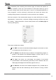
1 Configuration page (optionally), which contains the controls for setting the
time/date and for calibrating the built-in temperature probe. It also shows the
alarm log, the software version and the current IP address.
1.3 INSTALLATION
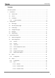
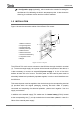
Figure 1 shows the connection outline of the InZennio Z41 screen:
Figure 1 Element diagram
The InZennio Z41 touch screen connects to the KNX bus through the built-in terminal
(1). To ensure enough supply as to power all the internal components of the device, it
is also necessary to connect an external DC power supply of 12, 24 or 29v which
delivers at least 150 mA of current. The KNX power and the external power must be
electrically isolated and provided by separate supplies, in order to avoid interference to
the KNX bus.
This external power must be supplied to the device through the corresponding terminal
(4) provided within the original packaging, ensuring that each cable is properly
connected and respecting the electrical polarities –positive and negative– from the
supply to the device.
In addition to the external supply, Z41 makes use of a button battery (LR44), located
at the corresponding slot (7), to help maintain the time and date updated in case of a
failure of the external power supply.
1.- KNX bus connection
2.- Programming button
3.- Programming LED
4.- External power input
5.- USB connection
6.- Ethernet connection
7.- Slot for the button battery
8.- Temperature sensor
9.- Magnet
5
4
8
2
1
7
3
9
6