
User manual


InZennio Z41
http://www.zennio.com Tecnical Support: http://zennioenglish.zendesk.com
11
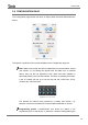
Last, the “SW Version” box shows the version of the application program
currently loaded to the device.
The Status page will also show up during bus failures in case the external power (12-
24-29v) is not interrupted.
Note: although the device will not turn functional until it is powered with the external
supply, the KNX bus power should be enough to perform downloads from ETS
(application program, group addresses, etc.).
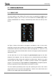
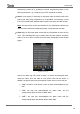
A brief press on the programming button (2) will make the device enter the
programming mode. The programming LED (3) will then light in red. On the contrary,
if this button is held while the device gets connected to the bus, Z41 will enter the
secure mode. In such case, the programming LED will blink in red colour.
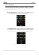
Connectors (5) and (6) are provided for firmware updates (see section 1.3.1) and
eventually for future functionality.
For detailed information about the technical features of Z41, as well as on security and
installation procedures, please refer to the device Datasheet, included within the
device packaging and also available at http://www.zennio.com.
1.3.1 FIRMWARE UPDATES
Z41 incorporates two different microcontrollers. One of them is focused on
interfacing with the KNX bus and on running the application program itself, while the
second one is dedicated to running the firmware that implements the operating system
and the management of the peripherals.
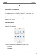
Therefore, an eventual update of Z41 may consist in two phases:
Downloading the new application program (from ETS),
Downloading the new firmware.
Two alternative methods are provided for the latter: the connection of a flash memory
drive to the USB slot (see 6 in Figure 1) through the proper adapter, or the connection
of an Ethernet network cable (see 6 in Figure 1). For further details on the firmware
update process, please refer to the specific document “Z41 – USB/Ethernet firmware
update”, available at http://www.zennio.com.