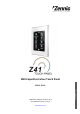
KNX Capacitive Colour Touch Panel Application Program Version: [3.3] User Manual Version: [3.3]_b www.zennio.
InZennio Z41 DOCUMENT UPDATES Version Changes Page(s) Minor text revision. - Icon list restructuring. - 3.3_b Changes in the application program: • Push notifications on alarm events are now sent to mobile devices. 3.3_a • New function: gas/water consumption monitor. Changes in the application program: 3.1_a • New functions: time/date periodic sending and chrono-thermostat.
InZennio Z41 backlight (total, partial or none) on inactivity. • Support added for TrueType fonts. • Compatibility with Greek and Cyrillic characters. • Driver update to offer compatibility with newer capacitive touch panels. • Minor changes in the handling of graphics, themes and transitions between themes. • “Lock” icon added to the Profile and Configuration pages when security protection has been set to them. • Interruption of the inactivity timeout counter if a popup windows is active.
InZennio Z41 CONTENTS Document Updates ....................................................................................................................... 2 Contents ........................................................................................................................................ 4 1 Introduction .......................................................................................................................... 6 1.1 InZennio Z41 ...........................................
InZennio Z41 3.5 3.4.2.2 1-button Control....................................................................................... 44 3.4.2.3 2-button Control....................................................................................... 46 3.4.2.4 Climate Control......................................................................................... 56 3.4.2.5 Other......................................................................................................... 64 Configuration ...
InZennio Z41 1 INTRODUCTION 1.1 InZennio Z41 InZennio Z41 is an easily and intuitively controllable high-performance colour touch screen. Its built-in features and functions make it the ideal solution for integral room control in hotels, offices or any other environments where controlling climate systems, lighting systems, shutters, scenes, etc. is required. The most outstanding features of InZennio Z41 are: 4.1 inch backlit capacitive touch panel.
InZennio Z41 Function Z41 1.x General-purpose pages 2 Specific-purpose pages (climate, scenes, timers) 4 Z41 2.x 3.0 3.1 3.3 6 (***) 6 (***) 6 (***) 6 (***) 48 (*) 48 (*) 48 (*) 48 (*) Binary indicators (text / icon) Enumerated indicators (text / icon) Numerical indicators (percentage, floating point, etc.) (**) Chronological data log for numerical indicators 1-button controls (binary, scene, percentage, floating point, etc.
InZennio Z41 1.2 Z41 3.x (AND LATER VERSIONS) Versions 3.3 and later of the Z41 application program feature the following functions: 6 General-Purpose Pages, with up to 8 Fully-Customisable Boxes each, which the integrator may configure as indicators or controls. Indicators: o Binary (icon or text). o Signed integer (8 / 16 bits). o Enumerated (icon or text). o Scaling (percentage). o Unsigned integer (8 / 16 bits). o Floating point (16 bits).
InZennio Z41 1 Configuration Page (optionally), which contains the controls for setting the time/date, for calibrating the built-in temperature probe and for pairing the device with a remote IP application. It also shows the alarm log, the software version and the current IP address. Note: Z41 3.x supports Latin, Arab, Chinese, Korean, Japanese, Greek, Cyrillic and Hebrew characters for the on-screen, customisable labels.
InZennio Z41 and respecting the electrical polarities –positive and negative– from the supply to the device. In addition to the external supply, Z41 makes use of a button battery, located at the corresponding slot (7), to help maintain the time and date updated in case of a failure of the external power supply.
InZennio Z41 synchronisation of the device during the start-up. Once it reaches 100%, the Status page will disappear and the Menu page will come up. The “Ethernet” box shows the IP address assigned to Z41, provided that an Ethernet cable has been attached (6) and the network is running a DHCP server. Last, the “SW Version” box shows the version of the application program currently loaded to the device.
InZennio Z41 Two alternative methods are provided for the latter: the connection of a flash memory drive to the USB slot (see 5 in Figure 1) through the proper adapter, or the connection of an Ethernet network cable (see 6 in Figure 1). For further details on the firmware update process, please refer to the “Z41 – USB/Ethernet firmware update” specific document, available at www.zennio.com. http://www.zennio.com Tecnical Support: http://support.zennio.
InZennio Z41 2 CONFIGURATION 2.1 MENU PAGE The user interface of the InZennio Z41 touch screen is organised into pages (up to eight different pages), each of which can be accessed from the Menu page, which (unless the contrary has been parameterised) is automatically shown after the start-up. Figure 3 Menu Page (example) As Figure 3 shows, the access to the pages is provided by a set of icons, which may show other (smaller) icons overlaid, such as an exclamation or a lock.
InZennio Z41 Figure 4 Menu button 2.2 GENERAL-PURPOSE PAGES The integrator can make use of up to 6 general-purpose pages, each of which can hold up to 8 different indicators or controls (with no restrictions for combining them) which will show inside the pages, automatically distributed or not, according to page parameterisation. For more details on the box distribution, refer to section 2.6.
InZennio Z41 Theme: desired colour combination, among eight different options: Figure 6 Themes Melody: desired tune (among three different options) for the beeps emitted on button presses or as a feedback on action executions. One more possibility is to make these beeps silent (alarm beeps will still work). Note that the labels of the controls in the Profile page, as well as the title of the page itself, are customisable in ETS.
InZennio Z41 2.4 CONFIGURATION PAGE The Configuration page lets the user know or adjust certain technical values about the device. Figure 7 Configuration Page The specific controls that can be made available for the Configuration page are: Date / Time: even though the device implements two communication objects (see section 3.1) for setting the internal time and date from an external device, they can also be adjusted (if such option has been enabled by parameter) directly from the user interface.
InZennio Z41 programming mode as by pressing the actual programming button of the device (see section 1.3) in case the rear of Z41 cannot be accessed. Reset: holding this button for a few seconds (i.e., a long press is required) sets the device back to a certain state, which can be set in ETS: ETS Reset Device: similar to a device reset from ETS, with the subsequent reset of the object values, alarm controls, timers, etc. Z41 Reboot: simple device reset, with no data loss (zeroing).
InZennio Z41 “ON”: the alarm is still active or has not been acknowledged by the user. “OK”: the user has acknowledged the alarm event, but the corresponding object is still in the alarm state. “OFF”: the user has acknowledged the alarm event and the corresponding object has already left the alarm state. For more information on alarms, see epigraph g) in section 3.4.2.5. IP Address: in case the device has been connected to an IP network through an Ethernet cable (see section 1.
InZennio Z41 2.5 BACKLIGHT In order to prevent unnecessary power consumptions while the device is idle, Z41 automatically fades partially out the backlight of the screen after two minutes without any user interaction. Next, after three more minutes of inactivity (i.e., after five minutes of inactivity), the backlight is completely turned off. While partially or totally faded out, any press on the screen will bring back the normal light level.
InZennio Z41 Figure 11 Dynamic Distribution of the enabled boxes http://www.zennio.com Tecnical Support: http://support.zennio.
InZennio Z41 3 ETS PARAMETERISATION To begin with the parameterisation of InZennio Z41, once the ETS program is running it is necessary to import the product database (Z41 application program). Next, the device is added to the project and, after right-clicking on the name of the device, the option “Edit parameters” must be selected to start the configuration process. The next sections explain in depth the ETS parameterisation of the device.
InZennio Z41 Note: although the DPT of this object considers a field for setting the day of the week, Z41 calculates it from the date and therefore ignores that field. [General] Date: 3-byte object for setting the internal date of the device, for example, by linking it to a KNX clock. This object also allows read requests, so the current date of the device can be checked. It is also automatically sent after date changes made by the user from the screen itself.
InZennio Z41 General, Security, Touch lock, Internal temperature sensor, Ethernet, Energy monitor objects, White-channel objects. Firmware Update. Menu, which will contain one more screen by default: Configuration, from which it will be possible to activate and configure each of the six general-purpose pages of the device (see section 2.2).
InZennio Z41 3.2 MAIN CONFIGURATION This tab is divided into multiple screens, all of which contain a set of global parameters regarding the general functionality of the device, and therefore not specifically related to a particular page of the user interface. 3.2.1 GENERAL The General screen contains the following parameters: Figure 14 General (Main Configuration)Power Supply Voltage: lets the integrator specify the particular voltage of the external supply powering Z41.
InZennio Z41 download. The final user will have the option to switch the scheme from the Profile page (see section 2.3), unless such option is disabled by parameter. Show Time: sets whether the current time (according to the internal clock) should show in the upper left corner of every page. The default is “Yes”. Screen Illumination: lets defining whether the backlight should behave during inactivity according to section 2.
InZennio Z41 letters or numbers) should be entered, so each of the characters will represent one weekday. The default value is “MTWTFSS”, according to the initial letters of the day names in English. Label for “Time ON”: field that permits customising the label that will be shown within the configuration pages of the weekly timers (see epigraph e) in section 3.4.2.5), next to the checkbox that enables/disables the sending of the switch-on order. The default value is “Time ON”.
InZennio Z41 whether the access to each page will be protected by one password or another, or remain unprotected – every page can be independently configured. Figure 16 shows the “enter password” dialog shown to the user when trying to access a protected page. Figure 16 Password Insertion Dialog (for password protected pages) In case of setting up two levels, the first one is assumed to be enclosed by the second one.
InZennio Z41 Important: the password insertion dialog features a specific option (lower left button) that lets the user change, in runtime, the passwords originally set by parameter. After accessing this option and prior to typing the new password, the user will be required to type the corresponding old password (level 1 or level 2).
InZennio Z41 Label for “Repeat password”: message shown when the user is required to re-type the new password. By default, “Repeat password”. Label for “Updated”: message shown to the user as a confirmation of the password change. By default, “Updated”. Buttons that lead to a protected page from the Menu page (see section 2.1) will show a little lock icon overlaid on their lower left corner. 3.2.
InZennio Z41 • Time to Activate the Welcome Object: minimum time of inactivity (in minutes) before a new press on the touch panel triggers the sending of the welcome object. By default, it is 1 minute. Figure 19 Touch Lock (Time to activate the welcome object configuration – 1 bit object) If “Scene” is selected, the [General] Scenes: Send object, already enabled in the beginning, will work as the welcome object.
InZennio Z41 3.2.4 INTERNAL TEMPERATURE SENSOR Figure 21 Internal Temperature Sensor (Main Configuration) This screen permits configuring the internal temperature sensor of the device. Three parameters are provided for this: Sensor Calibration: permits setting a certain correction over the values thrown by the internal temperature probe.
InZennio Z41 3.2.5 ETHERNET Figure 22 Ethernet (Main Configuration) The Ethernet tab permits configuring the Ethernet network interface of Z41. Therefore, from this parameter screen, it is possible to specifically enable the remote control function (see ANNEX I. Controlling Z41 Remotely via ) by marking the Remote Control through the Internet checkbox.
InZennio Z41 3.2.6 CONSUMPTION MONITOR OBJECTS Figure 23 Consumption Monitor Objects (Main Configuration) This screen contains six checkboxes, each of which permits enabling or disabling one communication “channel” that may be used for bus reception of consumption reports. Each channel can be set to monitor energy or water/gas consumption.
InZennio Z41 3.2.7 WHITE-CHANNEL OBJECTS Figure 24 White-Channel Objects (Main Configuration) This screen contains four checkboxes that allow the integrator to enable or disable up to four 1-byte communication objects independently, named [RGBW] White Channel x, through which regulation orders (expressed as percentage values) may be sent to the white colour channels of one or more RGBW light dimmers.
InZennio Z41 before the firmware download starts. This password, consisting in four numerical figures, needs to be set in ETS by the integrator: Figure 26 Password-Protected Update Note: reading the specific user manual of the firmware update process available at the Zennio webpage is encouraged, as it contains particular remarks regarding the password protection. http://www.zennio.com Tecnical Support: http://support.zennio.
InZennio Z41 3.3 MENU 3.3.1 CONFIGURATION Figure 27 Configuration (Menu) The Configuration screen, under the Menu tab, permits configuring the Menu page itself, as well as a set of general options related to the enabled pages that can be accessed from the Menu page. The parameters available are: Title: text field that defines the title that will be shown on the top of the Menu page.
InZennio Z41 3.4 PAGE n When any of the general-purpose pages is enabled from the Configuration screen under the Menu tab, a new tab named Page n will appear, where n is the number of the page. Under this tab, one screen (Configuration) will be initially displayed to let the integrator enable or disable any of the boxes in the page. Depending on that, more parameter screens will appear.
InZennio Z41 Icon: sets the icon that will represent the page in the Menu page. Note: a list with all the icons available in Z41 can be found in document “Z41 Icon list”, available at www.zennio.com. Protected: dropdown list that allows setting whether the access to the page will be protected by password or not. Depending on the security levels configured (one or two; see section 3.2.2) this list will contain the following options: One level: No: the page will not be protected by password.
InZennio Z41 This screen contains the following parameters: Label: identifying title for the box.
InZennio Z41 Therefore, when the device receives the values “0” or “1” through the aforementioned object, the box will show one icon or another. Note: a list with all the icons available in Z41 can be found in document “Z41 Icon list”, available at www.zennio.com. b) Binary Indicator (Text) The box will behave as a binary state indicator. Each of the two states will be shown in the box through a different label.
InZennio Z41 allows setting which icon will be shown in the box upon the reception of which value through the communication object. Example: a three-state enumerated indicator (“3” under “# Enum”) is parameterised as follows: Value 1 = “1” Icon 1 = “One” Value 2 = “3” Icon 2 = “Two” Value 3 = “5” Icon 3 = “Three” When the [Pn][Bi] Enumerated Indicator object receives the value “1”, the box will show icon “One”. When it receives the value “3”, icon “Two” will be shown.
InZennio Z41 permanently displays the value of a certain communication object, which is enabled when the function is assigned to the box. Function Range Related object 1-byte (unsigned int.) 0– 255 [Pn][Bi] 1-byte unsigned int indicator 1-byte (signed int.) -128 – 127 [Pn][Bi] 1-byte signed int indicator Percentage indicator 0% – 100% [Pn][Bi] Percentage indicator 2-byte (unsigned int.) 0 – 65535 [Pn][Bi] 2-byte unsigned int indicator 2-byte (signed int.
InZennio Z41 Figure 36 Indicator implementing the Log Function Boxes showing this icon let the user press them, which will bring up a pop-up window similar to Figure 37.
InZennio Z41 3.4.2.2 1-BUTTON CONTROL Boxes configured as 1-button controls show one centred button and a title. Figure 39 1-Button Control (Box) The desired function must be selected through the Function parameter. The available functions and the parameters related to each are: a) Binary Control The central button of the box will react to user presses by sending a binary value to the bus through the [Pn][Bi] Binary control object, which turns visible as soon as this function is assigned to the box.
InZennio Z41 • Hold 0 – Release 1: one “0” will be sent when the button press starts, and one “1” as soon as the button is released. • Hold 1 – Release 0: one “1” will be sent when the button press starts, and one “0” as soon as the button is released. Finally, the dropdown list next to Button (in the middle) permits selecting the icon to be displayed inside the button. Note: a list with all the icons available in Z41 can be found in document “Z41 Icon list”, available at www.zennio.com.
InZennio Z41 Note: a list with all the icons available in Z41 can be found in document “Z41 Icon list”, available at www.zennio.com. c) Scene Control In this case, the central button of the box will react to user presses by sending a scene value to the KNX bus through the [General] Scenes: send object, which is enabled by default. Parameter Scene number permits specifying the number of the scene (1 – 64) to be sent.
InZennio Z41 As a general rule, most of the 2-button controls permit configuring a pair of parameters, Left button and Right button, each containing a dropdown list for the selection of the desired icons to be displayed inside the buttons in the box. Notes: A list with all the icons available in Z41 can be found in document “Z41 Icon list”, available at www.zennio.com. When multiple presses are made consecutively on the buttons of a control that regulates (e.g.
InZennio Z41 Off Icon and On Icon: dropdown lists for the selection of the icons that will represent the two states (0 / 1) of the [Pn][Bi] Binary Indicator object, which gets automatically updated whenever an order is sent through the control object. It may also receive values from the bus.
InZennio Z41 Figure 46 Enumerated Control (Icon) The parameters available are: # Enums: number of states (up to 6) that will be distinguished. For every distinguished state, the parameters Value and Icon will become available, in order to relate every significant value of the communication object to a certain icon that will represent it. Value j: numerical value (0 – 255) that will be sent through the control object when the user, after pressing the buttons, sets the control box to state j.
InZennio Z41 Figure 47 Enumerated Control (Text) The parameters available are: # Enums: number of states (up to 6) that will be distinguished. For every distinguished state, the parameters Value and Icon will become available, in order to relate every significant value of the communication object to a certain icon that will represent it. Value j: value (0 – 255) that will be sent through the control object when the user, after pressing the buttons, sets the control box to state j.
InZennio Z41 Range Control object Status object 1-byte (unsigned int.) 0 – 255 [Pn][Bi] 1-byte unsigned int control [Pn][Bi] 1-byte unsigned int indicator 1-byte (signed int.) -128 – 127 [Pn][Bi] 1-byte signed int control [Pn][Bi] 1-byte signed int indicator Percentage control 0% – 100% [Pn][Bi] Percentage control [Pn][Bi] Percentage indicator 2-byte (unsigned int.) 0 – 65535 [Pn][Bi] 2-byte unsigned int control [Pn][Bi] 2-byte unsigned int indicator 2-byte (signed int.
InZennio Z41 decrease button. Maximum Value: sets which value from the available range will be the maximum value permitted by the control after a number of presses on the increase button.. Short Increment: sets the increase or decrease to be applied to the current value on every short press over the increase or decrease buttons, respectively (i.e., the smaller the increment is, the more presses will be required).
InZennio Z41 Through the Scene parameter it is possible to assign each of the two buttons (left / right) the number of the scene to be sent (1 – 64).
InZennio Z41 updated on user presses) so it receives the value 100% when the shutter is completely down, and the value 0% when it is totally up. On their side, control orders will be sent through one of the two remaining objects: Orders to move the shutter up/down (completely) are sent through [Pn][Bi] Move Shutter after a long press on the corresponding button. Value “0” represents the move up order, while “1” represents the move down order.
InZennio Z41 Setting up a box as a dimming control brings up the objects [Pn][Bi] Light Indicator (1 byte), [Pn][Bi] Light On/Off (1 bit) and [Pn][Bi] Light Dimming (4 bits). The former acts as the dimming status object, which is required to be linked to the analogous object from the dimmer and whose value, in percentage, will be permanently reflected in the box.
InZennio Z41 stop order arrives (such order is sent by Z41 when the user releases the button). Due to this behaviour, it is advised to parameterise dimming steps of 100%, so that the user can perform a complete dimming (from totally off to totally on, or vice versa) or a partial dimming by simply holding the button and then releasing it as soon as he gets the desired light level, therefore with no need of performing successive long presses for regulations greater than the parameterised step. 3.4.2.
InZennio Z41 the bus will be sent a progressively decreased value until the parameterisable minimum setpoint value has been reached. The parameters available are: Action: sets which of the two buttons will permit increasing the setpoint value and which one will permit decreasing it. Options are “Left decrease, Right increase” (default) and “Left increase, Right decrease”. Setpoint Type: it may be “Absolute” (default), “Relative (1-bit object)” or “Relative (Float Object)”.
InZennio Z41 Finally, when “Relative (float object)” is selected, the control will send 2byte floating point values. However, these values will correspond to the particular increment or decrement (or offset) to be applied each time. This offset refers to a base temperature and will always be a multiple of 0.5ºC. As the user touches the increase/decrease buttons in the box, this offset will vary, always within a certain range defined through the Minimum Offset and Maximum Offset parameters.
InZennio Z41 back to 34.5ºC. On the second button press, the value “9” will be sent, and the setpoint will become 34ºC. And so on until an offset of “-10” (setpoint of 15ºC) is reached. From that moment, any further presses on the decrease button will re-send the value “-10” and the setpoint will remain at 15ºC.
InZennio Z41 Figure 57 Heat/Cool Mode Type Two mode control types are possible: the Heat / Cool control type and the Extended (HVAC) control type. Selecting the former or the latter is possible through the Mode Type parameter.Heat / Cool Selecting this type of mode control turns the box into a 2-button control one of which will activate the Heat mode, while the other one will activate the Cool mode. A centred indicator will reflect, as an icon, the currently active mode.
InZennio Z41 Up to five modes (Heat, Cool, Auto, Fan and Dry) are available, each of which can be enabled/disabled in ETS by means of the proper checkbox, which permits setting which of all the five extended modes will be included into the sequential scrolling implemented by the buttons. Figure 60 Extended Mode When this type of mode control is assigned to the box, two 1-byte communication objects are enabled: the [Pn][Bi] Mode Control control object, and the [Pn][Bi] Mode Indicator status object.
InZennio Z41 c) Fan This function implements a 2-button (increase / decrease) fan control, as well as an icon indicator. Figure 61. Fan Control When this function is assigned to the box, a binary control object ([Pn][Bi] Fan Control) and a 1-byte status object ([Pn][Bi] Fan Indicator) are enabled. The former will be sending the value “1” to the bus when the user touches the increase button, while the value “0” will be sent when the decrease button is touched.
InZennio Z41 • Auto / Min / Med / Max: a level of 0% will be interpreted as the Auto state; levels between 1% and 33%, both included, correspond to the minimum state; levels between 34% and 66% will be considered as the medium state; and a value of 67% or more will correspond to the maximum state.
InZennio Z41 that corresponds to the mode that the user selects by touching the buttons (see Table 7), while the status object (which can receive values from the bus although it gets self-updated as well on button presses) will determine the indicative icon represented in the box at any time. If this object receives an unrecognised value from the bus, no icon will be displayed in the indicator.
InZennio Z41 a) RGB This function is intended for sending orders to thee-colour LED light regulators, such as LUMENTO X3 RGB from Zennio. Figure 65 RGB When the function is assigned to the box, the following parameters come up: Object Type: permits selecting what type of object will be used for controlling the light level of the RGB channels. It may be “Three single colour objects (DPT 5.001)” (by default) or “One RGB object (DPT 232.600)”.
InZennio Z41 Regarding the RGB control boxes themselves, a central label will permanently show, as a percentage, the current light level (which is determined by the channel with the highest current light level). This indicator gets updated automatically as the user interacts with the box, but is also conditioned by the values received from the bus through the already described objects.
InZennio Z41 b) RGBW Although totally analogous to the function just described, the RGBW control additionally permits controlling one extra channel specifically for white light, intended for dimmers that implement such function, such as LUMENTO X4 RGBW from Zennio.
InZennio Z41 Figure 69 RGBW (Box) Nevertheless, when the colour palette of an RGBW box is brought up, a forth increase/decrease regulator is shown together with the three regulators shown in the case of the RGB control boxes: Figure 70 RGBW Colour Palette c) Consumption Monitor This function permits making use of one of the boxes of Z41 as a monitor of energy or water / gas consumption –which may be reported by devices such as KES or KCI from Zennio– and in particular, as a monitor of the evolution of t
InZennio Z41 When the user touches any of these boxes, a pop-up window similar to the next figure will be shown. Evolution of the Power (or Flow) Consumption Instant Value of the Energy (or volume), CO2 and Cost Objects. Zoom Level Validation / Reset / Refresh Buttons Figure 73 Consumption Monitor. Pop-Up Window.
InZennio Z41 Cost: determines whether the pop-up window should show the instant value of the [Consumption x] Cost object or not. When this function is assigned to the box, two 1-bit communication objects show up: [Pn][Bi] Energy Monitor: Request and [Pn][Bi] Energy Monitor: Reset.
InZennio Z41 Validation / Refresh / Reset buttons: permit, respectively, closing the popup window, sending a reset order (value “1” through the [Pn][Bi] Energy Monitor: Reset object) and requesting an updated consumption report (value “1” through the [Pn][Bi] Energy Monitor: Request object).
InZennio Z41 Timer Type Selector: two-button control that permits switching through the following options: Timer inactive. Timer active (every day). Timer active (no repetition). Timer active (countdown). Time Selector: depending on the selected timer type, permits setting the time for the automated sending, or the length of the countdown.
InZennio Z41 certain time on certain days (on a weekly basis). Figure 77 Weekly Timer The difference between the daily and the weekly timers is that the latter does not permit the countdown-based sending, although it does permit that a timebased sending takes place every week, on the days selected by the user. Figure 78 Weekly Timer (Box). Hence, when pressing on the box, a window similar to Figure 79 will pop up.
InZennio Z41 Note: if instead of the sending of a binary value, the sending of a scene value has been parameterised, only one checkbox and one time selector will be shown, so the user can enable/disable the sending of the scene value and, if enabled, set the desired time. Time Selector: let the user set the time at which the automatic sending will take place.
InZennio Z41 f) Chrono-thermostat: Boxes configured as chrono-thermostats let the final user schedule the timed sending of temperature setpoint orders (preceded by switch-on orders) or switch- off orders to a thermostat through the KNX bus. To that end, it is necessary to configure the following two parameters: Figure 80 Chrono-thermostat Minimum Setpoint Value: minimum setpoint value the user will be able to set. Range: [-20, 95] x 1ºC. Default value: 18ºC.
InZennio Z41 Figure 82 Chrono-thermostat (pop up) Each box configured as a chrono-thermostat contains four pages with six customisable timers each, being possible for the user to configure up to 24 timed actions. The buttons on the bottom of the window let switching across the four pages, as well as closing the pop-up window (button ).
InZennio Z41 On power failures and ETS downloads, chrono-thermostat boxes behave the same as other user-defined timers: the user configuration will not be lost, although after an ETS download it will be necessary to enable the chronothermostat manually.
InZennio Z41 Figure 84 Alarm (Box). The intermitting exclamation means that the alarm is active and unconfirmed. However, alarm boxes implement an additional binary object, [Pn][Bi] Alarm Confirmation, intended for receiving the value “1” from the bus, which will be interpreted as an acknowledgement of the alarm, thus making the icon intermittence stop.
InZennio Z41 Consequently, alarm boxes permit configuring the following parameters: Trigger: defines the value that will trigger the alarm (“0” or “1”; it is “1” by default), i.e., the value that, when received through [Pn][Bi] Alarm Trigger, should be interpreted by Z41 as an alarm situation. Implicitly, this parameter also defines the inverse “no alarm” value. Periodic Monitoring: activates (“Yes”) or deactivates (“No”, default option) periodic monitoring of the alarm trigger object.
InZennio Z41 3.5 PROFILE PAGE The Profile Page tab contains a sole screen, Configuration. 3.5.1 CONFIGURATION This screen permits the integrator configure the controls that will be available for the final user within the Profile page (see section 2.3), as well as the label that will identify them on the screen. Note that the Profile page itself can be activated or hidden from the Configuration screen, under the Menu tab (see section 3.3.1).
InZennio Z41 3.6 CONFIGURATION PAGE The Configuration Page tab contains a sole screen, Configuration. 3.6.1 CONFIGURATION This screen permits the integrator configure the controls that will be available for the final user within the Configuration page (see section 2.4), as well as the label that will identify them on the screen. Note that the Configuration page itself can be activated or hidden from the Configuration screen, under the Menu tab (see section 3.3.1).
InZennio Z41 3.7 THERMOSTAT n Figure 88 Configuration Screen (Thermostat n) When the functions “Thermostat 1” and “Thermostat 2” from the General screen under the Main configuration tab are enabled, the integrator will be shown two more tabs, both similar to each other, for the parameterisation of these functions independently. Under each of the tabs, a set of screens (Configuration, Setpoint, etc.) is provided to define the type of the thermostatic control the user will be performing from Z41.
InZennio Z41 ANNEX I. CONTROLLING Z41 REMOTELY VIA IP Versions 3.x and later of the Z41 application program feature an IP communication mechanism that makes it possible to perform actions over the device and to control its functions remotely by means of specific applications that communicate with Z41 through IP networks, in an equivalent manner as if the device were actually being controlled on site.
InZennio Z41 Indicator Meaning No network connection available. No Internet access available. Waiting for the Remote Control service. Connection and service OK. Remote control in process (remote device currently connected). Table 8 Service States Note that the decision of disabling back the Device Pairing parameter or not after the pairing process is up to the integrator, depending on whether the final user needs or not to be allowed to pair their Z41 with further remote applications in the future.
InZennio Z41 Figure 90 Device Pairing dialog window On a short press, the Pairing Code Request button sends a Pairing Code request, which will be responded with an alphanumeric key word that Z41 will show on the upper section of the window, unless a communication error takes place (in such case, the word “ERROR” will be displayed on the screen). The user will be required to enter this key word on the remote application in order to set the link with Z41.
InZennio Z41 Alarm activation: a box that has been assigned the Alarm function has either received the alarm trigger value from the KNX bus, or exceeded the cyclical monitoring period. Alarm confirmation: a box with an active alarm has been acknowledged by the user. Alarm deactivation: a box that has already been acknowledged by the user has also received the no-alarm trigger value. Therefore, the alarm has been deactivated and acknowledged.
InZennio Z41 REMOTE APPLICATIONS For instructions on configuring and using the available remote applications, please refer to the “Z41 Remote” specific document, available at the Zennio home site: http://www.zennio.com. http://www.zennio.com Tecnical Support: http://support.zennio.
InZennio Z41 ANNEX II. COMMUNICATION OBJECTS ”Functional range” shows the values that, with independence of any other values permitted by the bus according to the object size, may be of any use or have a particular meaning because of the specifications or restrictions from both the KNX standard or the application program itself.
InZennio Z41 Number Size I/O Flags Data Type (DPT) Functional range Name 670760.96 1 Byte I C--WU DPT_Scaling 0% - 100% [PX][BX] Fan Indicator 1 Byte I C--WU DPT_Scaling 0% - 100% [PX][BX] Fan Indicator 2 Bytes I C--WU DPT_Value_Temp 1 Bit I C--WU DPT_Heat_Cool 0/1 -273.00 - 670760.
InZennio Z41 Number 114, 123, 132, 141, 10, 22, 34, 46, 58, 70, 82, 117, 126, 135, 144, 150 13, 25, 37, 49, 61, 73, 85, 120, 129, 138, 147, 16, 28, 40, 52, 64, 76, 88, 19, 31, 43, 55, 67, 79, 91, http://www.zennio.com Size I/O Flags Data Type (DPT) Functional range 2 Bytes O CTR-- DPT_Value_2_Ucount 0 - 65535 2 Bytes O CTR-- -32768 - 32767 -32768 - 32767 2 Bytes O CTR-- 9.xxx -671088.64 – 670760.
InZennio Z41 Number Size I/O Flags Data Type (DPT) 94, 97, 100, 103, 106, 109, 112, 115, 118, 121, 124, 127, 130, 133, 136, 139, 142, 145, 148, 151 Functional range Name Function 0x4 (Dec. by 12%) 0x5 (Dec. by 6%) 0x6 (Dec. by 3%) 0x7 (Dec. by 1%) 0x8 (Stop) 0x9 (Inc. by 100%) 0xA (Inc. by 50%) 0xB (Inc. by 25%) 0xC (Inc. by 12%) 0xD (Inc. by 6%) 0xE (Inc. by 3%) 0xF (Inc.
InZennio Z41 Number Size I/O Flags Data Type (DPT) 2 Bytes I C--W- DPT_Value_Temp Functional range Name 163, 190 1 Bit I C--W- DPT_Step 0/1 164, 191 2 Bytes I C--W- DPT_Value_Tempd -670760.00 – 670760.00 165, 192 2 Bytes O CTR-- DPT_Value_Temp -273.00 – 670760.00 [TX] Setpoint Status Current setpoint 166, 193 2 Bytes O CTR-- DPT_Value_Temp -273.00 – 670760.00 [TX] Basic Setpoint Status Current basic setpoint 167, 194 2 Bytes O CTR-- DPT_Value_Tempd -670760.
InZennio Z41 Number Size I/O Flags Data Type (DPT) Functional range -670760.00 – 670760.00 0% - 100% 209, 213, 217, 221, 225, 229 2 Bytes I C--W- Currency (non-standardized datapoint type) 230, 231, 232, 233 1 Byte I/O CTRWU DPT_Scaling http://www.zennio.com Name Function [Consumption X] Cost Local Currency [RGBW] White Channel X 0-100% Tecnical Support: http://support.zennio.
Join and send us your inquiries about Zennio devices: http://support.zennio.com Zennio Avance y Tecnología S.L. C/ Río Jarama, 132. Nave P-8.11 45007 Toledo (Spain). Tel. +34 925 232 002. Fax. +34 925 337 310. www.zennio.com info@zennio.