
Operation Manual


ZENNiO AVANCE Y TECNOLOGÍA vwww.zennio.com
5
5
Technical Alarms
General panel configuration
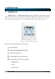
4 binary inputs for the connection of push buttons or switches/sensors.
Control through an IR remote control
1.2. INSTALLATION
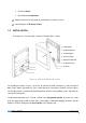
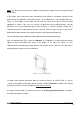
In the figure 1.2, the connection scheme of InZennio Z38i is shown:
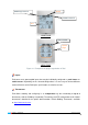
Figure 1.2. InZennio Z38i Elements scheme
For installing the device, first it is necessary to connect the KNX connector (1) and the terminal
block for the inputs connection (4). Once carried put these connections, the basic enclosure piece
must be placed into a standard squared/rounded box, with the corresponding screws and fixing the
cover of the touch panel.
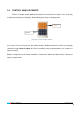
The programming button (2) is used to set Z38i in the programming mode, by means of a short
push (the programming LED (3) lights red). If this button is held while plugging the device into de
KNX bus, InZennio Z38i goes into secure mode. The LED blinks red.
1.- KNX connector
2.- Programming button
3.- Programming LED
4.- Inputs connection
5.- Display and Tactile area
6.- Temperature sensor
7.- IR receiver