PRODUCT MANUAL InZennio Z38i KNX Touch Panel ZN1VI-TP38i Program version: 2.
INDEX Document updates ......................................................................................................................................... 3 1. 2. 3. Introduction ............................................................................................................................................ 4 1.1. InZennio Z38i................................................................................................................................... 4 1.2. Installation ........
DOCUMENT UPDATES Version 2.2a Modifications Reorganization of the information in Section 1 into two independent sections: 1. Introduction and 2. Configuration More information in section 1.2. Installation Version 1.1 of Building Thermostat has been integrated New format of the product manuals ZENNiO AVANCE Y TECNOLOGÍA Page(s) 4-9 5,6 All vwww.zennio.
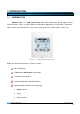
1. INTRODUCTION 1.1. INZENNIO Z38I InZennio Z38i is an LCD Touch Panel with Room Thermostat, Binary Inputs and IR Receiver built-in. Z38i is a great solution for demanding applications in hotel rooms, apartments, offices, and in any room where it is necessary to manage climate, shutters, lights, scenes, etc. Figure 1.1. InZennio Z38i touch panel Below, the most relevant features of Z38i are shown: 3.
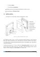
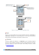
Technical Alarms General panel configuration 4 binary inputs for the connection of push buttons or switches/sensors. Control through an IR remote control 1.2. INSTALLATION In the figure 1.2, the connection scheme of InZennio Z38i is shown: 1.- KNX connector 2.- Programming button 3.- Programming LED 4.- Inputs connection 5.- Display and Tactile area 6.- Temperature sensor 7.- IR receiver Figure 1.2.
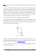
Note: This device does not need any additional external power supply since it is powered through the KNX bus. In the factory status of the panel, after connecting it to the KNX bus and before carrying out any programming, the calibration screen will be shown. Once calibrated (see steps-to-follow to do so in figure 1.3), it will appear in the header the text "Z38i 2.2", where the version of the pre-installed application is shown; in this case, the version 2.2.
2. CONFIGURATION 2.1. PRODUCT The panel InZennio Z38i allows controlling a set of functionalities in a domotic installation in a simple and intuitive way. There are a set of parameters that refer to the general working of the panel, such as: lighting, header configuration, internal temperature sensor, password, etc. The configuration of Z38i is completed with: Pages The information shown in the Display is organized into pages; every page consists of several parametrizable boxes and a header.
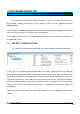
Header MENU Page shortout HOME 2 shortout Box HOME PAGE Back to HOME Specific pages access MENU PAGE Figure 2.1. Example of the pages organization in Z38i Inputs Z38i counts on 4 opto-coupled inputs that may be individually configured as push button or switch/sensor. Depending on the selected configuration, it is necessary to connect different external elements to the Z38i inputs: push buttons or switches/sensors.
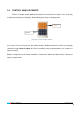
2.2. CONTROL USING IR REMOTE Z38i has a remote control (optional) that allows the control of the functions in the same way as directly touching over the Display. Short and long-pressings are distinguished. Zone 1 Zone 2 Figure 2.2. Z38i remote control As it can be seen in the Figure 2.2, the remote control is divided in two zones, which may remotely control the pages Home or Home 2 of Z38i, according to the parameterization (see section 3.2. Remote control).
3. ETS PARAMETERIZATION For starting to parameterize the Z38i touch panel it is necessary, once the ETS program has been opened, importing the data base of the product (version 2.2 of the application program InZennio Z38i). Next, the device is added to the project where desired. Click the right mouse button on the device and select "Edit parameters" for starting with the configuration.
Figure 3.2. Configuration screen by default As it can be seen in the figure 3.2, the configuration screen has the following main windows: General: to enable and configure the basic functionalities of the panel and the remote control. Pages: to enable and configure individually each available page: Home, Home 2 and specific pages. Inputs: to enable and configure individually each input of the controller. Thermostats: to enable and configure individually each thermostat of the controller.
3.2. GENERAL The General window allows enabling and configuring the basic functionalities of the panel and the remote control. The basic functions that can be configured in the section General are the following: Display lighting: This function allows establishing the luminosity status of the display, by parameter, choosing between: Always lighting: the display remains always ON, even when the it is not in use.
Header: It is possible to select by parameter what to show in the display header, choosing among: Show Temperature, Show Time and/or Show Date (all of them are enabled by default). If "Show Date" is enabled ("Yes"), it appears a new field to indicate through 7 characters the weekday initials. Only capital letters and numbers can be used. Both the date and the week-day will appear on any page header, when the “Time Zone” is pressed. (See Figure 3.4).
Figure 3.5. Remote control options Zone 1: To enable and associate this IR controller zone to any of the Home or Home 2 pages. Zone 2: To enable and associate this IR controller zone to any of the Home or Home 2 pages. Note: If remote controller is disabled in the parameterization, a press key over any button DOES NOT have effect in the touch panel. Internal Temp.
Default password is 1234. Figure 3.7. Password In the field "Allow password changing", one can choose whether the password can be modified in the panel itself or not. If this change is not allowed, the password cam only be changed through ETS (parameters). If the password changing is enabled, the following steps must be carried out to properly change it (see also figure 3.8): 1.- Press NEW. In the upper part of the box the word “OLD” will appear and the old password has to be written. 2.
3.3. PAGES In this section it is possible to enable and configure individually each page to be implemented in Z38i. Figure 3.9. Pages configuration Every enabled page has some parametrizable fields: Name: This field allow users to associate a name to any of the InZennio Z38i pages; this name will appear on any of the page headers the user is moving through (12 free characters are available to set the name). Note: The only page which cannot be renamed is the MENU one (to access Specific Pages).
3.3.1. HOME AND HOME 2 PAGES These two pages are intended to parametrize their boxes so that it is easy to access the most common used functions when controlling an installation. Figure 3.10. Home page Home a Home 2 pages have 6 parametrizable boxes each, to be configured as: binary control, light control, shutter control, climate control, 1 byte control, scene control, temperature control, binary indicator, 1 byte indicator, floating indicator, security control and presence simulator.
INDICATOR Figure 3.11. Example of configuration of Home page Next, all the possible configurations for the Home and Home 2 boxes are explained. Note: For all the options shown below it is possible to configure, through the parameter Icon, the icon or pair of icons that will be drawn, pixel by pixel, over the representation of each button in the display. To know the list of available icons, please consult the specific documentation "List of controls and indicators".
Toggle: sending the values "0" and "1" in a switched way to the KNX bus through the corresponding object every time the button 1 is pressed (short or long press). Button 2: The configuration options are the same as for Button 1. The two buttons will transmit data independently, but they will do so through the same communication object ("[Home x; Box y] Binary control").
on the buttons), where depending on the “dimming step” set, keeping the button pressed will reduce or increase the brightness on the controlled lamps. Dimming step: Seven different regulation levels are available for this duty. A long press on the display buttons will reduce or increase the brightness level step by step the percentage set in this parameter; once the desired level is reached, stop pressing the button on the display to keep the desired value.
The shutter control is carried out as follows: Decrease button: a long press moves down the shutter while a short press stops the shutter, sending the value "1" through the objects "[Home x; Box y] Move shutter" and "[Home x; Box y] Stop shutter", respectively. Increase button: a long press moves up the shutter while a short press stops the shutter, sending the value "0" through the objects "[Home x; Box y] Move shutter" and "[Home x; Box y] Stop shutter", respectively.
Control type: to select the climate function to be controlled: Mode type: Cool-Heat or Auto-Heat-Dry-Fan-Cool Fan: the indicator type can be selected (no indicator, percentage or integer). Swing Icon: A pair of icons can be associated to the page box. Note: Depending on the selected option, a communication object associated to the specific box will appear in the ETS environment; the same object type corresponding the selected option.
It exists, choosing this option, the possibility to shorten the sending range in the parameterization process with parameters “Minimum Value” and “Maximum Value”. Icon: A pair of icons can be associated to the page box. Scene control: Scenes or “lifestyles” consist of a synchronized activation of some devices in the domotic installation, so that different predefined atmospheres are generated. There is an only Communication Object associated with scenes: "[General] Scenes".
Activate the Alarm System. Once the scene is defined, every time we run it, a predefined atmosphere is generated. How does a user modify and learn a scene, with the devices used in the scene described above? For example if the user wants this instead: Turn all the lights Off except one (the one to remain ON, will be a guiding light). Turn Off the Heating and the A/C Systems Activate the Alarm System. The way to do this: 1. Run the scene to be modified. 2.
Icon: A pair of icons can be associated to the page box. Binary indicator: This control enables a binary status indicator on the display box. An icon, specifically enabled for this function, may be associated to the page box when a “0” is received through the 1 bit Communication Object "[Home x; Box y] Binary indicator". Same case if data received is a “1”.
Type: Permits specify the output data type as percentage (%) or as numeric value (0 - 255). Floating point indicator: Floating Point is a real number representation method that can be adapted to the order of magnitude of the value represented.
In this case, the Panel will not send any binary data to the bus unless the correct password is entered. Icon: A pair of icons can be associated to the page box. Indicator: by activating this parameter, a status indicator will be inserted between both buttons: Nothing, ON/OFF, 0/1 Presence simulator: This function is designed to simulate presence in a house. Once the devices on the KNX installation have been correctly parameterized, two new Communication Objects become active.
The parameters to be configured are: Starting/Finish time: to establish the time (hours and minutes) when the presence simulation will start and finish (provided that the functionality has been enabled through the object "[Home x; Box y] Presence simulation"). Note: The stating and the finish time must be different values in order to the presence simulation work properly. Minimum/Maximum ON/OFF time: To adjust by parameter the minimum and maximum ON/OFF time for the devices on the installation.
The way to parameterize any of the 5 boxes of a Specific Page to control scenes is exactly the same as that described in section 3.3.1. Scene control. To obtain further information on this topic, please read the corresponding section. Timers The daily/weekly programming of certain events the user wants them to happen on the KNX installation is much easier using this Page. Figure 3.13.
Every enabled box for the timers control will have its own output "Channel" (output object of the timers) through which the communication object in charge of controlling the timer will go. The following parameters can be configured for every enabled box: Name: This field allows a user to associate a name with the corresponding box in the page. (11 free characters are available to set the name). Linked to scenes: When this box is enabled, a user can control Scenes by mean of a programming.
And the timers page 3 this way: -Box 3 Linked to Scene number 11. Only for ON In case that all these timers send their own scene at the same time, the only scene that will be sent is the one linked to the last box of the last Timer page configured, in this example, Z38i will send the scene number 11 (linked to the Box 3, in the Timers page 3). Climate Air Conditioning and Fan Coil Control have been unified in a unique Specific Page called “Climate”.
The number of Specific Pages to control Climate Systems will mainly depend on the number of different Systems to control in the installation. Figure 3.15. Specific page: Climate Every time a user enables a specific “Climate” page, two different configurable fields become available: Name: This field allows a user to associate a name with the corresponding box in the page. (11 free characters are available to set the name). Icon: A pair of icons can be associated to the page box.
BOX 1 (On/Off): This box is enabled in the Climate page to send the orders to switch on/switch off the climate system connected to the KNX bus. The communication objects related to the switching on/off pf the system are enabled ("On/Off Sending" and "On/Off Reception"). Moreover, a new 1 bit object appears: "Activity indicator" to be associated, through a same group address, to the 1-bit control variables of the climate system.
Absolute temperature: the objects “[Clima x] Setpoint Sending” and “[Clima x] Setpoint Reception” are enabled, to send and receive, respectively, the setpoint temperature to be set and the current setpoint of the climate system. Short or long pressings over the box are allowed to set the desired setpoint (the temperature will change in 0.5ºC to 0.5ºC, no matter the type of pressing). It is necessary to set a lower and upper limits, in ºC, for the setpoint temperature.
mode (“1” for Heating or “0” for Cooling) will be sent to the climate system. Via the object “Mode Reception”, the panel will receive the status of the current mode of the climate system and will update the central indicator of the box with the corresponding figure of the current working mode. For the Auto-Heat-Fry-Fan-Cool configuration: the 1-byte objects “[Clima x] Mode Sending” and “[Clima x] Mode Reception”.
known at every moment the current working mode of the system (for achieving this, it will be necessary to link with the same group address the mode objects of the climate system and the object "Special Modes reception"). It is possible to include the sending/reception of the special mode Protection, by parameter. The mode sending is not carried out immediately. By the time the special mode changes, it also does the centrol mode indicator.
Alarm trigger value: To choose the value that will trigger the alarm (“0” or “1”). This will mainly depend on the parameterization of the warning device installed. Cyclical monitoring: The state of the detection devices will be cyclically monitored by enabling this parameter. This parameter assures two features: the detection of incidents in the minor time possible and the security that the device of detection is properly working.
3.3.4. CONFIGURATION PAGE This is a specific page where the user can adjust some basic parameters of the screen (time, date, contrast, etc.). Figure 3.18. Configuration page All of them have the parametrizable field "Name", which allows associating a name to the corresponding box in the page. (11 free characters are available to set the name). Next, the different function of each box in the “Configuration Page” is described. Note: The disabled boxes are configured as blank boxes in the Page.
The refresh rate is 1 minute. When the display recovers from a bus Power failure, this will show the time it had just before the incident. Note I: When a Power bus failure occurs, please have on mind the delay this implies to correct it. Note II: There are different KNX devices on the market which can synchronize periodically the time and date of every single device in the installation. Such devices can be really useful when the installation is based on any kind of Schedule programming.
Figure 3.19. Configuration page aspect 3.4. INPUTS Z38i has 4 binary inputs to be configured as push button o switch/sensor, connecting the corresponding devices. Once the input is enabled, the access to the corresponding configuration window appears in the main menu according to the configured type of input. 3.4.1.
Figure 3.20. Inputs: Push button Next, the configuration options for the inputs as push buttons are shown. For each of them there are the following configurable common fields: Threshold time: this parameter defines the time limit, in tenths of second, where a short turns into a long press. Response delay (short press): This parameter sets the time to wait for the object to be sent to the bus since the action on the input took place. I.e.
a) Short press No action: Z38i does not carry out any action when short pressing over the push button connected to its input.
Note I: The “Stop shutter” configuration include 3 options of step up, step down and switched step to lamellas control; but if the shutter does not have directional lamellas available, any of the three options will stop the shutter. Note II: If the option "up/down (switched)" is chosen to short press, “stop shutter” action will not be able to be done in any point of the trajectory with other short key press over the same input.
b) Long press The configuration options are the same as in Short Press. 3.4.2. SWITCH/SENSOR When configuring an input as switching/sensor, it is necessary to select the action to carry out in the falling edge and the rising edge. Figure 3.21. Inputs: Switch/Sensor The available options are: Rising edge: select the sending value when this edge happens: Nothing (no action is performed). 0: the object "[Ix] Edge" is sent to the KNX bus with value "0".
Sending of "1" Delay: specify the time, in seconds, after which the value "1" will be sent, once received the corresponding order. Periodical sending of "0": define a cyclical sending, in seconds, of the value "0". The value 0 indicates that the periodical sending is not activated. Periodical sending of "1": define a cyclical sending, in seconds, of the value "1". The value 0 indicates that the periodical sending is not activated.
4. ANNEX I.
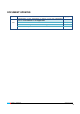
SECTION NUMBER SIZE IN/OUT VALUES FLAGS RANGE 54-65 66-77 1byte 1byte NAME 1st TIME RESET O T Indifferent Indifferent O T Indifferent Indifferent D DESCRIPTION [Home x Box x] Precise Light dimming 1-byte dimmer control [Home x Box x] 1 byte control 1 byte generic control [Home x Box x] Mode control 0=Aut;1=Heat;3=Cool;9=Fan; 14=Dry O T Indifferent Indifferent I WU 0 Last [Home x Box x] Light Indicator 0%=Off; 100%=On I WU 0 Last [Home x Box x] Shutter position 0%=
SECTION SPECIFIC X (CLIMATE) VALUES NUMBER SIZE IN/OUT 138-141 1 bit I WU [Clima x] Mode reception 0=Cool; 1=Heat 138-141 1 byte I WU [Clima x] Mode reception 0=Aut;1=Heat;3=Cool;9=Fan;14=Dry 142-145 2 bytes I WU [Clima x] Setpoint reception Value returned by the machine 146-149 1 byte O RT [Clima x] Special Mode sending 1=Comfort; 2=Standby; 3=Economy 146-149 1 byte O RT [Clima x] Special Mode sending 1=Comfort; 2=Standby; 3=Economy; 4=Protection 150-153 1 byte I WTU
SECTION INPUTS NUMBER 178-185 (ODD) SIZE 1 bit, 4 bits, 1 byte 186-187 2 bytes 188-189 2 bytes 190-191 1 byte 192-199 1 bit 1 bit THERMOSTAT IN/OUT O FLAGS WT RANGE - VALUES 1st TIME - NAME RESET DESCRIPTION [Ix] [Long Press] Move Up/Down Shutter Long Pr. -> Switching "0/1" [Ix] [Long Press] Stop/Step Up Shutter Long Pr. -> Sending of "0" [Ix] [Long Press] Stop/Step Down Shutter Long Pr. -> Sending of "1" [Ix] [Long Press] Stop/Step Shutter (switched) Long Pr.
DOCUMENTATION TECHNICAL SUPPORT TECHNICAL http://zennioenglish.zendesk.