
Operating instructions


6
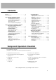
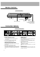
Monitor Controls
Connection Options
VOL.MENU
INPUT
SELECT
ON/OFF
Main Power Button
INPUT SELECT Button
VOLUME (F,G) Buttons
Power Standby Indicator
Illuminates red in standby mode,
Illuminates green when the
Monitor is turned on
Remote Control Sensor
MENU Button
E, D Buttons
R
( )
( )
( )
( )
L
REMOTE
CONTROL
RGB2 INPUT
(DIGITAL RGB INPUT)
RGB1 INPUT
(PC/DTV INPUT)
RGB1 OUTPUT
(PC/DTV OUTPUT)
COMPONENT
(DVD/DTV INPUT)
RS-232C INPUT
(CONTROL/SERVICE)
EXTERNAL SPEAKER
LOCK
CONTROL
ON/ OFF
YP
B
P
R
(MONO)
R
AUDIO
L
R
AUDIO
L
S-VIDEO VIDEO INPUT
AC INPUT
AUDIO INPUT
AUDIO INPUT
AUDIO INPUT
12 3
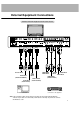
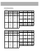
Front Panel Controls
Front Panel Controls
Back Connections Panel
Back Connections Panel
4 5 8
1. EXTERNAL SPEAKER (8 ohm output)
Connect to optional external speaker(s).
* For further information, refer to ‘Speaker & Speaker
Stand’ manual.
2. RS-232C INPUT (CONTROL/SERVICE) PORT
Connect to the RS-232C port on a PC.
3. AUDIO INPUT/RGB1 INPUT (PC/DTV INPUT)/
RGB2 INPUT (DIGITAL RGB INPUT) JACKS
Connect the monitor output connector of a PC to the appro-
priate input port.
4. RGB1 OUTPUT (PC/DTV OUTPUT) JACKS
You can watch the RGB1 signal on another monitor, connect
RGB1 OUTPUT (PC/DTV OUTPUT) to another monitor’s
PC input port. Note: In standby mode, RGB1 output does not
work.
5. CONTROL LOCK Switch
REMOTE CONTROL
When “CONTROL LOCK” is set to “ON”, the Monitor is oper-
able by the external control device.
6. COMPONENT (DVD/DTV INPUT)/AUDIO INPUT JACKS
7. AUDIO/VIDEO INPUT JACKS
Connect audio/video out from external equipment to these
jacks.
S-VIDEO INPUTS (S-VIDEO)
Connect video out from an S-VIDEO VCR to the S-VIDEO
input.
8. POWER CORD SOCKET
This Monitor operates on an AC power. The voltage is indi-
cated on the Specifications page. Never attempt to operate
the Monitor on DC power.
6 7