SERVICE MANUAL Model Series: L15V26 Product Type: Chassis: Manual Series: Manual Part #: Model Line: Product Year: LCD TV ML-012A CM154 923-03489 E 2002 CONTENTS Safety .......................................................... 2 General Info ................................................. 5 Servicing ................................................... 15 Parts ......................................................... 22 Diagrams .................................................... 27 Schematics .....
PRODUCT SAFETY 1. Immediately before handling any semiconductor component or semiconductor-equipped assembly, drain off any electrostatic charge on the body by touching a known earth ground. Alternatively, obtain and wear a commercially available discharging wrist strap device, which should be removed for potential shock reasons prior to applying power to the unit under test. PRODUCT SAFETY IMPORTANT SAFETY NOTICE This manual was prepared for use only by properly trained audiovisual service technicians.
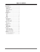
TABLE OF CONTENTS PRODUCT SAFETY ................................................ 2 TABLE OF CONTENTS ............................................ 3 GENERAL INFO ................................................... 5 SERVICE/WARRANTY ........................................ 5 FEATURES ..................................................... 5 SPECIFICATIONS ............................................. 5 COMPUTER CONNECTION ................................... 6 FRONT VIEW .......................................
-4-
GENERAL INFO NTSC TUNER Accepts standard United States broadcast video signals as designated by the National Television Standards Committee. HI-RES COMPONENT VIDEO Delivers the highest quality picture by breaking down video data into three separate signals—red, blue and luminance—before the data is sent to the television. PARENTAL CONTROL W/V-CHIP Programmable feature that uses the US standard content advisory system to exclude viewing of specific programs or program types.
GENERAL INFO SPECIAL FEATURES Note: When the PC is in the power saving mode, to also save energy, the monitor automatically switches to DPM mode. Picture In Picture (PIP) ................................. Yes DRP (Digital Reality Processor) ........................ Yes Soft-Touch ................................................... Yes LTI (Luminance Transient Improvement) ........... Yes Tri-lingual Menus ............. English, French, Spanish Auto Programming .........................................
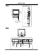
GENERAL INFO FRONT VIEW Side control p nel panel ch Channel buttons vol Volume buttons enter Enter button menu Menu button tv/video TV/Video button Remote control sensor Power/standby indicator Illuminates brightly when the TV is in standby mode. Dims when the TV is switched on.
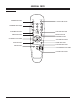
GENERAL INFO REMOTE CONTROL power tv/video POWER BUTTON NUMBER BUTTONS TV/VIDEO BUTTON 1 2 3 4 5 6 7 8 9 flashbk cc 0 FLASHBK BUTTON CAPTION BUTTON menu mute MUTE BUTTON ENTER BUTTON MENU BUTTON ch CHANNEL BUTTONS vol enter vol VOLUME BUTTONS mts ch sleep MTS BUTTON PIP BUTTON SLEEP BUTTON pip POSITION BUTTON position pip input ch PIP CHANNEL BUTTONS PIP INPUT BUTTON CM154 - 923-03489 8 L15V26 - GENERAL
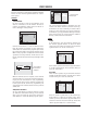
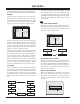
USER MENUS USER MENUS Channel Press the menu button repeatedly to display the available menus. Use the channel up/down buttons to select a menu option. CH. Auto program Manual program Fine TV 7 Memory Current channel is displayed CHANNEL AUTO PROGRAM For Auto program to work, the programming source must be connected to the TV and the TV must be receiving programming signals either over-the-air or from a cable-type service provider. Move Back The current channel number is displayed.
USER MENUS When the sleep time you want is displayed on the screen, don’t press the sleep button again. To check the remaining sleep time, press the sleep button once. To change sleep time setting, press the sleep button repeatedly to select time setting you want. If you turn the TV off after setting the sleep timer, the setting will be erased. Use the volume up button to select Hold or Run. Hold means the off Timer feature is not active and Run means it is.
USER MENUS Press the volume up and then use the volume up/ down buttons to make appropriate adjustments. Use the channel up/down button to select other options. Contrast, Brightness, Sharpness, and Color are adjustable from 0 to 100. Tint is adjustable from Red 50 to Green 50. Press the enter button to select. BALANCE While in the Sound menu, press the volume up and then use the channel up/down buttons to select the Balance option.
USER MENUS Press the enter button o accept and exit. This TV is programmed to remember the caption/text mode it was last set to, when you turn the POWER off. Special CH. Language Caption/Text Captions Auto off Key lock Parental Move PARENTAL CONTROL The Parental Control Function (V-Chip) is used to block program viewing based on the ratings sent by the broadcast station. The default setting is to allow all programs to be viewed.
USER MENUS KEY LOCK The TV can be set up so that it can only be used with the remote control. Press the volume up and then use the channel up/down buttons to select the Key lock option. Press the volume up and then use the channel up/down buttons to select on or off. Each press of channel up/down buttons toggles between on and off. This TV will remember which option it was last set to even if you turn the TV off.
- 14 -
SERVICING SERVICING TROUBLESHOOTING *HQHUDO )HDWXUHV 1R 6\PSWRP &DXVH &KHFN 3RLQW %XWWRQ GRHVQ·W IXQFWLRQ %URNHQ FRPSRQHQWV DQG VROGHULQJ RI WKHP 3 FRQQHFWRU HUURU &KHFN EXWWRQ ZLWK H\HV &KHFN DQG UHSDLU VROGHULQJ &KHFN DQG UHSDLU WKH 3 FRQQHFWRU 1R VFUHHQ ,QSXW HUURU RI LQYHUWHU FRQQHFWRU %HQG WKH SLQ OHJV RI 3 FRQQHFWRU ! UHFKHFN WKHP &KHFN DQG UHSDLU WKH ,& 6, 3 DQG 3LQ FRQQHFWRU EHLQJ VOLSSHG RXW &KHFN DQG IL[ 3 FRQQHFWRU &KHFN DQG IL
SERVICING PC INPUT MODE ADJUSTMENT ADJUSTMENTS Notes: (1) This set uses an AC adapter, so connect the adapter and the set correctly before adjustment. (2) The adjustment must be performed in the correct sequence. (3) The adjustment must be performed in the circumstance of 25+/-5C of temperature and 65+/-10% of relative humidity. (4) The input voltage of the receiver must keep 100~220V, 50/60Hz during adjustment. (5) The set must be operated for 30 minutes before adjustment.
SERVICING VIDEO MODE SETTINGS Tim ing of Mode Table * H[dot]/V[line] Mode VGA-60 VGA-67 VGA-72 H_Total 800 864 832 H_Display 640 640 656 H_Blanking 160 224 176 H_Sync 96 64 40 H Polarity NEG. NEG. NEG. H_Bp 48 96 120 H_Fp 16 64 16 H-Freq[KHz] 31.469 35 37.861 /Clk[MHz] 25.175 30.24 31.5 V_Total 525 525 520 V_Display 480 480 496 V_Blanking 45 45 24 V_Sync 2 3 3 V Polarity NEG NEG NEG V_Bp 33 39 20 V_Fp 10 3 1 VGA-75 VGA-85 SVGA-56 SVGA-60 840 832 1024 1056 640 640 800 800 200 192 224 256 64 56 72 128 NEG.
SERVICING ADJUSTMENT OPTIONS 2SWLRQ GDWD 35a$ 67 ELW 6<6 ELW 237,21 35 'DWD 7(;7 , ,, 69 723 6&$57 $ 67 6<6 237,21 35 'DWD 7(;7 , ,, 69 723 6&$57 $ 67 6<6
SERVICING 237,21 35 'DWD 7(;7 , ,, 69 723 6&$57 $ 67 6<6 237,21 35 'DWD 7(;7 , ,, 69 723 6&$57 $ 67 6<6
SERVICING 237,21 35 'DWD 237,21 35 'DWD 7(;7 , ,, 69 723 6&$57 $ 67 6<6 7(;7 , ,, 69 723 6&$57 $ 67 6<6
SERVICING 237,21 35 'DWD 7(;7 , ,, 69 723 6&$57 $ 67 6<6 2SWLRQ GDWD $&06a%%$&.
PARTS PARTS C333 0CK224DF56A This model is a Factory Service Repair model (in and out of warranty) and is covered by a one year warranty. For service, the end user should call 1-800-984-9349 for complete shipping and handling instructions (or call 1877-9ZENITH). Refer to the last page of the opguide for more information.
PARTS C650 C651 C652 C653 C654 0CE477DF618 0CE476DF618 0CQ1031N509 0CE107DF618 0CK224DF56A C655 0CK224DF56A C69 0CE105VK6DC C801 0CE476DK618 C802 0CE477DF618 C803 0CE477DF618 C804 0CE477DF618 C805 0CE477DF618 C806 0CE477DF618 C807 0CE477DF618 C808 0CE227DH618 C814 0CE107DH618 C815 0CE107DH618 C817 0CE475DK618 C902 0CE106SF6DC C904 0CE106SF6DC C906 0CE107SF6DC C909 0CE107SF6DC C911 0CE107SF6DC C915 0CE106SF6DC C935 0CE107SF6DC C970 0CE107SF6DC D1 0DD181009AB D2 0DD181009AB D601 0DD181009AB D602 0DD181009AB
PARTS L277 6210TCE001A L3 6210TCE001G L301 6210TCE001G L302 6210TCE001G L303 6210TCE001A L304 6210TCE001G L4 6210TCE001G L601 6210TCE001G L602 6210TCE001G L603 6210TCE001G L604 6210TCE001G L801 6210TCE001G L802 6140VB0004B L803 6140VB0004A L804 6210TCE001G L805 6210TCE001G L901 6210TCE001G L902 6210TCE001G L904 6210TCE001G L905 6210TCE001G L908 6210TCE001G L911 6210TCE001G L913 6210TCE001G L914 6210TCE001G L915 6210TCE001G L916 6210TCE001G L917 6210TCE001G L925 6210TCE001G LD1101 PA1101 CM154 - 923-034
PARTS RA930 RA931 SW1101 SW1101 SW1102 SW1103 SW1104 SW1105 SW1106 SW1107 T801 6170VTCA30A TU101 X1 156-A01P X301 6202VDT002E X601 156-A02M X901 6202VDT002B ZD101 0DZ330009BA ZD211 0DZRM00178A CM154 - 923-03489 MNR-14-E0A-J-101 100OHM 5% 0RRZVTA001A R E S I S T O R , D R A W I N G , MNR-14-E0A-J-101 100OHM 5% 0RRZVTA001A R E S I S T O R , D R A W I N G , MNR-14-E0A-J-101 100OHM 5% 140-313A SWITCH,TACT, TACT 2LEAD 100G(TA) 5V 0.001A HOR. 6600VM1001A SWITCH,PUSH, SDKLA1 ALPS UL/CSA 250V 5A VERT.
- 26 -
DIAGRAMS DIAGRAMS EXPLODED VIEW 10 14 15 9 3 1 2 11 4 5 6 7 8 12 13 CM154 - 923-03489 ITEM 1 2 3 4 5 6 7 8 9 10 11 12 13 14 15 27 PART NO.
DIAGRAMS WIRING DIAGRAM P902 CN3 P1 MAIN1 PWB P2 P202 P602 P601 CN1 CN2 P1103 P1101 P1 MAIN1 PWB P2 P202 CN3 P602 P601 CN1 CN2 P1103 P1101 CONNECTOR LCD MODULE 3P ---> INVERTER PCB CN2 LCD MODULE 3P ---> INVERTER PCB CN3 POWER S/W PCB P1103 --> MAIN PCB P202 POWER S/W PCB P1101 --> MAIN PCB P2 INVERTER ASSY CN1 --> MAIN PCB P1 SPEAKER (3P) --> MAIN PCB P602 SPEAKER (4P) --> MAIN PCB P601 CM154 - 923-03489 28 L15V26 - DIAGRAMS
PC-AUDIO INPUT L-SPK R-SPK 12V PC INPUT ....... .... Audio AMP LA4282 (TXT/CAPTION) (TXT/CAPTION) 6MHZ 6MHZ IC1 IC1 MICOM SCL/SDA H/P S-INPUT .... SIF_IN SIF_IN SC2_IN SC2_IN SC2_OUT SC2_OUT SC3_IN SC3_IN I2S I2S :: 22 ------18.432MHz--------18.432MHz--L-SPK/WOOFER L-SPK/WOOFER H/P, H/P, I2S I2S IC601 Audio Processor MSP-3440 8.0V 5.0V IC902 CPU 80C652 8bit SCL/SDA 5.0V V Y/ U/ V 4:2:2 L R VIDEO INPUT (DRP Processor) Processor) LGTV-1001 LGTV-1001 IC302 HH- FILTER FILTER 3.
PCB LAYOUTS PCB LAYOUTS MAIN PCB LAYOUT TOP CM154 - 923-03489 30 L15V26 - PCBS
PCB LAYOUTS MAIN PCB LAYOUT BOTTOM CM154 - 923-03489 31 L15V26 - PCBS
PCB LAYOUTS CONTROL PANEL PCB LAYOUT POWER SWITCH PCB LAYOUT CM154 - 923-03489 32 L15V26 - PCBS
Schematics L15V26 Main Micro Circuit 1/2 1 2 3 4 5 6 7 8 9 10 G F E D C B A CM154 - 923-03489 CRITICAL SAFETY COMPONENTS ARE IDENTIFIED BY THE SYMBOL REPLACE ONLY WITH PART NUMBERS SPECIFIED. . 33 NOTE: WAVEFORMS AND VOLTAGES WERE MEASURED AT 120VAC, CHANNEL 5, AND NSTC COLOR BARS.
L15V26 Signal Circuit 2/2 1 2 3 4 5 6 7 8 G F E D C B A CM154 - 923-03489 CRITICAL SAFETY COMPONENTS ARE IDENTIFIED BY THE SYMBOL REPLACE ONLY WITH PART NUMBERS SPECIFIED. . 34 NOTE: WAVEFORMS AND VOLTAGES WERE MEASURED AT 120VAC, CHANNEL 5, AND NSTC COLOR BARS.