
Service manual


12 PDP 40” - SERVICING
SERVICING
SERVICE MENU ADJUSTMENTS
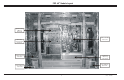
If the Main Video Scan Converter module (Part# 809-
10722) is installed the unit will come on when A/C is
applied. The EEPROM data will be in Factory default values.
The following charts and instructions will allow you to
set the EEPROM and make necessary adjustments. If the
unit will power on prior to the replacement of this Module
and the menus can be accessed it would be advisable to
record the data from the original EEPROM if possible.
The provided Service Remote must be used to make
adjustments or access the service menu.
Note: Equipment Needed: NTSC Pattern Generator and
DTV Pattern Generator.
ADJUSTMENTS MUST BE DONE IN NTSC AND DTV MODES
NTSC/PC Adjustments
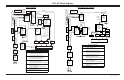
1. Depress the (in-start) key one time, the following menu
will appear.
2. The chart shows starting value settings for adjust-
ments.
3. Use the UP or DOWN keys to scroll through the menu
and the LEFT or RIGHT keys to make the adjustments.
4. To exit the service menu press the (enter) key one
time.
DTV Adjustments
1. To Enter this protion of the service menuwith the unit
on press the (adj) Key one time. With the unit off you
can press the (power on) key two times, this method
of access to this menu will automatically set Heat run
to WHITE and will allow you to make adjustments.
NOTE: “Heatrun” has the following settings: OFF, WHITE,
RED, BLUE, and GREEN.
These are for warm up of the unit as well as testing for
defects. This function will also remove minor burn in
of the display. NOT FOR SETTING RGB DRIVES.
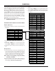
NP-00LE M28037K E.0
DTV NTSC
OPTION 48 48
CXA2101 0 0
CXA2101 STB
PHASE 12 30
H POSITION 0 0
V POSITION 12 0
OSD POSITION 13 13
PLL-GAIN 17 17
EEPROM INIT
Input Settings
OPTION 48
FKO REMOCOM ZENITH
FKO AREA USA
FKO LANGUAGE ENGLISH
FKO SYSTEM 3 SYS
FKO WOOFER OFF
CXA2101 0
VP 0 BCUT 9
VP 1 RCUT 7
VP 2 R-GAIN 10
VP 3 G-GAIN 10
VP 4 B-GAIN 9
VP 5 S CONTRAST 3
VP 6 S BRIGHT 0
VP 7 S-COLOR 6
VP 8 S-TINT 7
VP 9 S-SHARP 3
VP 10 CTI-LEVEL 1
VP 11 R-Y/R 6
VP 12 G-Y/R 10
VP 13 R-Y/B 9
VP 14 G-Y/B 5
VP 15 GAMA 5
VP 16 BLK-BOTTOM 15
VP 17 PRE/OVER 1
VP 18 D-TRAN 1
VP 19 D-PIC 2
VP 20 V-TC 2
VP 21 H-WIDTH 1
VP 22 D-COL 1
VP 23 HD-TC 0
VP 24 SHP-FO 1
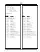
PC & NTSC Adjustments
2. The chart shows starting value settings for adjust-
ments.
3. Use the UP or DOWN keys to scroll through the menu
and the LEFT or RIGHT keys to make the adjustments.
4. To exit this portion of the service menu cycle power
off and on.
NTSC DTV
VP 0 HEATRUN OFF OFF
VP 1 CUTOFF-AUTO
VP 2 R-FINE 16 16
VP 3 G-FINE 16 16
VP 4 B-FINE 16 16
VP 5 R-GAIN 16 16
VP 6 G-GAIN 10 10
VP 7 B-GAIN 3 3
VP 8 R-CUT 151 161
VP 9 G-CUT 94 95
VP 10 B-CUT 25 26
VP 11 (NTSC) DVCO ADJ OFOO
VP 11 (DTV) AUTO PLL END
VP 12
Heatrun Adjustments