
Service manual


11 PDP 40” - SERVICING
SERVICING
3. Supply window Signal to TD-710 in pattern genera-
tor. [ When adjustment is operated manually, oper-
ate process (3) to (7) regular sequence, when ad-
justment is operated automatically perate process
(1) to (2).
4. Select STB CXA2101 by pressing SVC,ADJUST button
on Remote Control for adjustment.
5. To adjust Low Light, stick sensor to 9th
pattern(Dark). Select the B Cut/R Cut, then adjust
the B Cut/R Cut until color coordination becomes
X=0.280±0.003, Y=0.310±0.003 and color tempera-
ture becomes 8.800cK ± 500cK by pressing VOL+, -
button. (Adjust in B Cut 10±1, R Cut 6±1)
6. To adjust High Light, stick sensor to 2th
pattern(White). Select the R Gain/G Gain, then ad-
just the R Gain/G Gain until color coordination be-
comes X=0.280±0.003, Y=0.310±0.003 and color
temperature becomes 8.800cK ±500cK. (B-Gain fixa-
tion)
7. Confirm the result of the High Light adjustment. If
the deviation of High Light occur, operate the ad-
justment of Low Light and High Light again. (Ex-
pectation average adjustment data : B-Cut & RCut=
6±2, R-Gain/G-Gain=25±3)
8. Exit adjustment mode using A/V button.
ADJUSTMENT OF VIF-VCO COIL
RF Signal generator
- If any model don t have SECAM-L/L System, you should
not operate adjustment of VR101.
- Output of Power Supply = DC 5V
- Oscilloscope range = set 0.5V/div., 5msec/Div.(using
scope)
Adjustment 38.9MHz IF(B/G, D/K, I, L, M)
1. Input the signal of the signal generater(38.9MHz)
to TP105(IC102 pin 7) through 0.01uF(103) ca-
pacitor.
2. S1 : OFF, S2 : IN, S3 : OFF
3. Adjust voltage of the TP103 to 2.5 0.1V by adjust-
ing X106.
L VCO(Adjustment SECAM-L ) Adjustment —> Only SECAM
L model
1. After changing the signal of the signal generater to
34.25MHz, input the signal to TP102(IC102 pin 11)
through 0.01uF(103) capacitor.
2. S1 : on, S2 : off, S3 : ON
3. Adjust voltage of the TP103 to 2.5 0.1V by adjust-
ing VR101.
AGC ADJUSTMENT
1. Connect the signal of PAL-B/G 05ch. to Antenna
jack.
2. Connect Multi meter to point(J150) of AGC adjust-
ment.
3. Adjustment the voltage of Multi meter to 2.3 0.1V
by changing VR102.
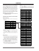
OPTION TABLE
Funtion of Line Service
1. Enter to SVC mode by using SVC button on the re-
mote control. To enter to the SVC mode,press the
“OK” button on RTBA10 local key ond “OK” button
on the remote control simultaneously. In MT-BA10
only,press the “INPUT” button and “OK” button on
remote control to enter to SVC mode.
2. Select the item by using the Quick View(Yellow)
button.
3. After adjusting,restore adjusted item in EEPROM by
using “OK” button and use the CYAN button to can-
cel the adjusted condition.
4. Select the program directly and input the data of
option by using the number button.
5. Line SVC-0(Hitrun&W/B Adj.mode)=> VSC EEPROM.
H/T RUN:OFF,WHITE,RED,GREEN,BLUE,OFF. A/C
SRT:Auto Cutoff. R/G/B Fine 16,R/G/B Gain 3,R/G/
B Cutoff 100
6. Line SVC-1(Phase&Position Adj.mode)=> VSC
EEPROM. Phase 15,H-Pos 32,V-Pos 32,Auto Posi-
tion
7. VSC CXA2101 Adj.mode)=> VSC EEPROM
8. STB CXA2101 Adj.mode)=> STB EEPROM
9. SOUND Adj.mode => VSC EEPROM
10. Option 1 Adj.mode => VSC EEPROM. Select it di-
rectly by using Teletext Size button.
11. Option 2 Adj.mode. Select it directly by using Tele-
text Hold button.