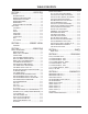
SERVICE MANUAL Product Type: Chassis: Manual Series: Manual Part #: Model Line: Product Year: Model Series: Digital Rear Projection ZP26/28 PV154 923-03506 E 2002 CONTENTS General Info ................................................. 1 Service Menu ................................................ 2 Servicing ..................................................... 3 Part List ...................................................... 4 Diagrams / PCB Layouts .................................. 5 Schematics ....
PRODUCT SAFETY SERVICING GUIDELINES FOR AUDIO-VIDEO PRODUCTS IMPORTANT SAFETY NOTICE A.C. Voltmeter This manual was prepared for use only by properly trained audio-video service technicians. When servicing this product, under no circumstances should the original design be modified or altered without permission from Zenith Electronics Corporation.
PRODUCT SAFETY SERVICING GUIDELINES FOR AUDIO-VIDEO PRODUCTS 5. Do not use freon-propelled chemicals. These can generate electrical charge sufficient to damage ES devices. CRT ANODE HIGH VOLTAGE MEASUREMENT PROCEDURE To prevent possible exposure to radiation caused by excessive CRT Anode voltage, the High Voltage Shutdown circuit senses the level of flyback pulse from “Flyback Transformer” representative of the actual high voltage on the CRT anode.
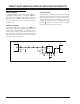
PRODUCT SAFETY SERVICING GUIDELINES FOR AUDIO-VIDEO PRODUCTS HOLD-DOWN CIRCUIT INFORMATION NORMAL CONDITION In normal condition, the DC voltage at point a is approximately 4.88V through pin 1 of P1407 (HV Block). The voltage at point b is approximately 4.86V. The voltage of pin 5 of IC404 is lower than the voltage of pin 6 (5.1V). The voltage of pin 7 is 0V and the transistor Q403 is off. ABNORMAL CONDITION In abnormal condition, the voltage of point b is much higher than normal voltage.
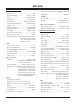
TABLE OF CONTENTS SECTION 1 .................... OVERVIEW SERVICE ADJUSTMENTS .................................. 3-16 ZP-25 CHASSIS ADJUSTMENT ORDER ............. 3-16 CHASSIS PRE-HEAT RUN ADJUSTMENTS .......... 3-17 CHASSIS CUT-OFF (SCREENS) ADJUSTMENT ..... 3-17 CHASSIS PRE-FOCUS ADJUSTMENT ................ 3-17 DCU CROSSHATCH PHASE ADJUSTMENT .......... 3-17 CHASSIS HORIZONTAL PHASE ....................... 3-17 CHASSIS TILT (RASTER INCLINATION) ............ 3-18 CHASSIS BEAM ALIGNMENT ADJUSTMENT .......
SECTION 1 OVERVIEW OVERVIEW R56W28 & R65W28 R50V26 & R60V26 The R56/65W28 and R50/60V26 are HDTV Monitors. This means that most of the components of a HDTV are present except for the ASTC tuner. An HDTV receiver or converter box is required to view an ASTC signal. The W28 models feature a 16:9 aspect ratio screen. But, it can display video in several different aspect ratios, including 16:9 and 4:3. More features and specifications are listed below.
OVERVIEW REMOTE CONTROL Transmitter Universal Remote w/Glow Channel & Volume Model Number ....................................... MBR5045 R50/60V26 SPECIFICATIONS VIDEO Picture Tubes .......................................... 7" LFM Resolution Display .......................... 540p or 1080i Mirror ........................................ 1st Surface Glass Lens System ..................................... Enhanced HD Tuning System ....................... NTSC + Up Converter Scan Velocity Modulation .......
OVERVIEW SPECIAL FEATURES HD Monitor Digital DisplayDisplays Digital Signals at 540p or 1080i (User Selects) Tri-lingual Menus ............ English, Spanish, French Other features .. Icon Menus, Source ID, Channel Labels, Parental Control with VChip, On/Off Timer, Flashback, CC, CC When Mute, 2 Level Mute, Channel Review, Channel Skip, Power Resume, On/Off Speaker Selection, Date/Time/Channel, Energy Star® APPROVALS UL, C-UL, NOM ....................................... UL, C-UL UPC Code ...................
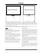
OVERVIEW FRONT CONNECTIONS menu source select - volume + - channel + power S-Video Video L/Mono R exit REAR CONNECTIONS Inputs 3 and 4 Y, PB, PR, and Audio L - R Component Video Some top-of-the-line DVD players use what is called “component video,” for extremely accurate picture reproduction. Refer to your DVD manual for further information. S-Video Input 1 and 2 Connections available for some high-end equipment that provides even better picture quality.
REMOTE CONTROL REMOTE BUTTON DESCRIPTIONS MODE INDICATOR LIGHTS Light indicates mode when keys are pressed. Part Number MBR6045A 924-10098 SOURCE Selects available TV sources. MODES TV, VCR, Cable, DVD, HD/STB Switches remote operating mode to control other devices. After pressing a Mode switch key, wait 2 - 3 seconds before pressing any other key. NUMBER KEYPAD 0 - 9 Selects channels directly and enters numerical values.
REMOTE CONTROL REMOTE BRAND CODES TVs Daewoo . . . . . . . 149 TV/VCR Combination Codes Funai TV/VCR. . . . 154 Zenith . . . . . . . . 101 121 149 152 Adventura TV/VCR . 154 Goldstar TV/VCR . . 153 172 Daewoo TV/VCR . . 148 Symphonic TV/VCR 154 Zenith TV/VCR . . . 150 152 153 154 172 VCRs Admiral . . . . . . . 261 Akai . . . . . . . . . . 292 717 718 719 720 General Electric . . 216 220 266 282 701 702 725 Orion . . . . . . . . . 250 Sears . . . . . . . . . 211 212 213 265 274 Go Video . . . .
REMOTE CODES REMOTE CONTROL Satellite Receivers Alphastar. . . . . . . 516 Hughes Network . . 514 RCA . . . . . . . . . . 510 517 Toshiba . . . . . . . . 509 512 Chaparral . . . . . . . 501 502 JVC . . . . . . . . . . 518 Realistic . . . . . . . 506 Uniden . . . . . . . . 522 Cheyenne. . . . . . . 502 Macom . . . . . . . . 314 Sierra I . . . . . . . . 502 United . . . . . . . . 344 Dishnet . . . . . . . . 515 Magnavox . . . . . . 521 Sierra II . . . . . . . 502 Zenith Drake. . . . .
REMOTE CONTROL OPERATING MODE KEY FUNCTIONS KEY NAME source light power tv vcr cable dvd hd/stb aspect 1 2 3 4 5 6 7 8 9 0 display mute volume (up) volume (down) channel (up) channel (down) flashbk split multi pip ch c skip sleep cc 923-03460 TV Mode VCR Mode Cable Mode DVD Mode HD/STB Mode TV Sources Lights Keys 5 Seconds TV On/Off Selects TV Selects VCR Selects Cable Selects DVD Selects HD/STB TV Sources Lights Keys 5 Sec VCR On/Off Selects TV Selects VCR Selects Cable Selects DVD Selects HD/STB
USER MENUS REMOTE CONTROL KEY NAME TV Mode VCR Mode Cable Mode DVD Mode HD/STB Mode TV Favorite Channels TV Menu Quit TV Select Up TV Select Down TV Adjust Left Favorite Channels TV Adjust Right Favorite Channels TV Menu Item Select TV Menu VCR VCR VCR VCR VCR Cable Page Down Cable Quit Cable/Sat Up Arrow Cable/Sat Down Arrw Cable/Sat Left Arrow N/A DVD DVD DVD DVD N/A HD/STB HD/STB HD/STB HD/STB theater record stop I<< skip skip >>I pause rew (rewind) play ff fav ch (Channel) quit up arrow dow
USER MENUS If certain CATV channels are not received clearly in CATV1 mode, set the source to CATV2 mode. USER MENUS SETUP CHANNEL ADD/DEL (DELETE) Customize your channel selection list: Add Channels not found by Scan (Channel Search), Delete channels you don’t watch. Channels will appear when using Channel Up/Down Press the MENU button on your remote to access the Setup menu. TRILINGUAL MENUS Press MENU to access the Setup menu. Use the DOWN arrow to choose Trilingual.
USER MENUS CLOCK SET Use the UP/DOWN arrow to choose Clock Set. Use the RIGHT arrow button to choose first the time option and use the UP/DOWN arrow buttons to adjust time options. Press the RIGHT arrow button and then use the UP/DOWN arrow buttons to adjust month/date/ year options. Press QUIT to save and exit. TO SET TIME SEL SETUP Trilingual Menus Signal Scan Use the RIGHT arrow button to access the Picture formats Menu.
USER MENUS Use the UP/DOWN arrows to choose an option. If you chose Ch Labels, press the RIGHT arrow button to access the preset channel label list and scroll through this list using the UP/DOWN arrow buttons. When you find the appropriate label for the channel, press the SELECT button. If you select Custom Channel, press the RIGHT arrow button once and then use the UP/DOWN arrow buttons to select individual letters and LEFT/RIGHT arrow buttons to choose placement of letters.
USER MENUS Notes • Favorite Channels are only available on ANT 1 source. • If Parental Control Ratings are locked, it will disable multiple channel insets (including the Favorite Channels POP-3 insets). • When POP-3 favorite channel is on, Closed Caption option will not appear. • If Closed Caption is set to Auto and Mute is on, Favorite Channels cannot be accessed.
USER MENUS SETUP Press MENU and then the RIGHT/LEFT arrow button to access the Special Menu. Press the UP/DOWN arrow to choose Parental Control and then press the RIGHT arrow button to activate Parental Control. When prompted, enter the default code 7777 from the number keypad. If you wish to change the code, select “Change Secret Code” and enter the new code through the number keypad. If you forget your code, just reenter “7777” to reset to factory preset code.
USER MENUS CAPTIONS Press MENU and the RIGHT/LEFT arrow button to access the Special Menu. Use the UP/DOWN arrow to choose Captions. Press the RIGHT arrow button to activate Captions option. Use the LEFT/RIGHT arrow to choose Display Off, On, or Auto option.
USER MENUS RESET Use the UP/DOWN arrow to choose Reset (Reset restores the levels to their original settings). Press SELECT to confirm your choice. PICTURE SETTINGS Press MENU and use the RIGHT/LEFT arrow button to access the Audio Menu. Use the UP/DOWN arrow to choose one of the following options. Use the RIGHT/ LEFT arrow buttons to adjust that option. • Bass: Increase/decrease lower-end sounds. • Treble: Increase/decrease higher-end sounds.
USER MENUS THEATER MENU POP-3 10 SEL SETUP SPECIAL VIDEO AUDIO THEATER 11 Theater Modes TV Surround Movies Music 12 Sports Reset Menu To Menu Bar To Exit Quit Main Picture POP-3 Channels THEATER MODES Press MENU and then the RIGHT/LEFT arrow button to access the Theater menu. Press DOWN arrow button to access the Theater Modes or Surround. To change Theater Modes, press RIGHT arrow button to choose Theater Modes. Use the UP/DOWN arrow buttons to choose which mode you prefer.
- 1-18 -
SECTION 3 CIRCUIT DESCRIPTIONS CIRCUIT DESCRIPTIONS POWER ON AND OFF The power supply runs all the time when AC is applied. The use of the power supply creating Stand-By Voltage supplies eliminates the need for a Stand-By transformer. The following explanation will describe the Turning ON and OFF of the projection television. The Microprocessor I001 generates the ON-OFF control signal from pin (53). The logic states of this pin are High = On and Low = Off.
CIRCUIT DESCRIPTIONS · Shorted SW +5V (IC02) on Signal PWB through PROTECT 1 to (D940) on Sub Power Supply PWB ohm, however it could be any low ohm value. When the current demand increases, the voltage drop across the resistor increases. If the voltage drop is sufficient to reduce the voltage on the base of the transistor, the transistor will conduct, producing a Shutdown signal that is directed to the appropriate circuit. NOTE: PROTECT 1 will not go below 2.2V even if the 5V or the 3.3V lines are open.
CIRCUIT DESCRIPTIONS HOT GROUND SIDE SHUT DOWN SENSING CIRCUITS (INTERNAL TO IP01) LATCHED SHUT DOWN MONITORS (AC must be removed to recover) 1. Pin 4 is monitored for Over Voltage internal to IP01. 2. IP01 itself is monitored for Excessive Heat. This block is labeled T.P.O. (Thermal Protection Overload). RECOVERING SHUT DOWN INPUT (Driver IC will recover on it’s own when trouble is removed) 3.
CIRCUIT DESCRIPTIONS sistor turns Off, generating a High on its collector. This output High is routed through D705 to pin (1) of Connector PQD2 called PROTECT and Shut Down occurs as described above. called PROTECT and Shut Down occurs as described above. 9. Side Pincushion failure generating a High. (D702, and D703). The Side Pin Cushion op-amp circuit is comprised of I701. If a problem occurs in this circuit it creates a High from pin 7 of I701.
CIRCUIT DESCRIPTIONS NOTE: If the 5.5V or the 3.3V regulators OPEN, the set will not go into shut down, they must have a short to produce a shut down input on PROTECT 1. The set will shut down after the Screen go excessively bright, but this is from the 115V over current sensor, not PROTECT 1. When the power supply is in Stand By, the Short Detection circuit could activate. By turning off Q919, no accidental shut down operation can occur.
CIRCUIT DESCRIPTIONS LED USAGE The Visual LEDs are useful in Trouble Shooting. Without removing the back cover, some diagnostics can be made. By observing the operation of the Red and Green LEDs, the technician can determine if the Deflection Power Supply is running. By monitoring these LEDs at turn on, one can determine if a line is loaded. If an LED tries to light then goes off, or only lights dimly, a loaded condition should be considered.
CIRCUIT DESCRIPTIONS V BLK The Vertical Blanking pulse is generated from the Vertical output IC, I601 pin (11). This pulse normally operates at 21V P/P. IR The Infrared Pulses coming from the remote control are routed through the Deflection PWB to the Digital Convergence Unit. During DCAM (Digital Convergence Adjustment Mode), the Remote Control provides manipulation pulses for the DCU. DIG RGB/ BUSY This indicates Digital RGB and BUSY.
CIRCUIT DESCRIPTIONS 30Kv HV 30,000 volts DC supplied to the CRTs anodes. TO DEFLECTION YOKES Horizontal and Vertical deflection wave forms driving the deflection yokes. MAGIC SWITCH Output from the DAC1 (I006 pin 7) when the customer selects HD FOCUS from the customer’s menu. This energizes HD FOCUS, (Magic Focus). SERVICE ONLY SWITCH Enters the Digital Convergence Adjustment Mode, (DCAM). · H.
CIRCUIT DESCRIPTIONS A sample of the High Voltage is output from the Flyback transformer TH01 pin (12). This voltage is sent to pin (9) of the High Voltage Driver IC IH01. This voltage is compared to the reference voltage available at pin (12). If there is a difference between the two voltages, an error voltage is generated and output from pin (10) and input again at pin (11) where it manipulates the PWM (Pulse Width Modulation) signal producing the Horizontal Drive signal output from pin (1).
CIRCUIT DESCRIPTIONS • HD FOCUS SENSORS AND INTERFACE • MICROPROCESSOR • RAINFOREST IC (Video Processor). • SERVICE ONLY SWITCH • MAGIC FOCUS (HD Focus) activation control. THE DIGITAL CONVERGENCE UNIT (DCU) The DCU is the heart of the Digital convergence circuit. Held within are all the necessary components for generating the necessary waveforms for correction, and associated memories for the adjustment data and Magic Focus Data. The Block above shows the relationship of the DCU to the rest of the set.
CIRCUIT DESCRIPTIONS the BUSY line. As long as the BUSY line is active, the Main Microprocessor ignores the IR signal. ON SCREEN DISPLAY PATH: MICROPROCESSOR SOURCE FOR OSD: The On Screen Display signal path is shown with the normal OSD information such as Channel Numbers, Volume Graphic Bar, Main Menu, sent from the Main Microprocessor to the Rainforest IC IC01 pins 37, 38 and 39. These are positive pulses, about 5 V p/p and about 3uS in length dependant upon their actual horizontal time for display.
CIRCUIT DESCRIPTIONS The Microprocessor communicates with the following ICs: The ABL voltage is determined by the current draw through the Flyback transformer. As the picture brightness becomes brighter or increases, the demand for replacement of the High Voltage being consumed is greater. In this case, the flyback will work harder and the current through the Flyback increases. This in turn will decrease the ABL voltage. The ABL voltage is inversely proportionate to screen brightness.
CIRCUIT DESCRIPTIONS in the EEPROM, such as the window for Closed Caption detection. Data and Clock lines are SDA1 from pin (2) of the Microprocessor to pin (5) of the EEPROM and SCL2 from pin (3) of the Microprocessor to pin (6) of the EEPROM. Data travels in both directions on the Data line. FLEX CONVERTER UC01 The projection television is capable of displaying NTSC as well as ATSC (DTV) including HD (High Definition).
CIRCUIT DESCRIPTIONS Communication from the Microprocessor via pins (59) SDA2 and (60) SCL2 to the Rainforest IC pins (31 and 30) respectively. ON THE TERMINAL PWB and a little more dark just before it arrives. This gives the impression that the signal pops out of the screen or a 3D effect. The Microprocessor communicates with the 3D Y/C IC via I2C bus data and clock. The communications ports from the Microprocessor are pins 59 (SDA2) and 60 (SCL2) to the 3D Y/C I301 pins (59 and 60) respectively.
CIRCUIT DESCRIPTIONS The Microprocessor uses a combination of I2C Bus communication and the Serial Data, Clock and Load lines for control. The I2C communication scheme only requires 2 lines for control. These lines are called SDA and SCL. Serial Data and Serial Clock respectively. SRS AUDIO +29V REGULATOR INDICATED BY D912. The SRS Audio +29V supply is generated from pin (8) of T901. This output is rectified by D910 and filtered by C915.
SERVICE ADJUSTMENTS SERVICE ADJUSTMENTS ZP-25 CHASSIS ADJUSTMENT ORDER Always follow the sequence below. Order Adjustment Item Screen Format Signal DCU Data Pre HEAT (30 Minutes) Normal Mode NTSC N/A 1 Cut Off Normal Mode NTSC N/A 2 Pre Focus Lens and Static Normal Mode NTSC N/A 3 DCU Phase Data Setting Normal Mode NTSC N/A 5 Horz. Position Adj. (Coarse) Normal Mode NTSC N/A 6 Horz. Position Adj. (Coarse) 1080i HD 2.
SERVICE ADJUSTMENTS CHASSIS PRE-HEAT RUN ADJUSTMENTS PRESET EACH ADJUSTMENT VR TO THE CONDITION SHOWN: BEFORE PRE HEAT RUN. 1. Red and Green Drive VR on the CRT PWB. This is part of the I2C Service Menu. Set each to 3F. To Enter Service Menu, press the SOURCE button and hold, then press the Power Button. Set comes on and displays Service Menu. 2. SCREEN VR ON FOCUS PACK. Pre Set fully counterclockwise. 3. Focus VR on focus pack Pre Set fully clockwise. 4.
SERVICE ADJUSTMENTS BLUE: 4. Remove cover or PTS short from BLUE and cover the RED CRT. Align BLUE with GREEN. [+/- 1mm tolerance when compared to Green] After Completion: 5. Tighten DY Yoke Screws to 12+/-2 kg-cm. 6. REMOVE ALL COVERS or SHORTS on the PTS connectors. 7. Turn the Power Off. 6. Select Item H POSI and adjust the data so that the center of Video matches the location of the Digital Crosshatch pattern noted in step {4}. 7. Exit from the I2C Menu. 1080I HD MODE ADJUSTMENT: 1.
SERVICE ADJUSTMENTS Left of Center and Blue is offset Right of center. Please use the following information to accurately offset Red and Blue from center. Also see Overlay Dimensions for further details. PREPARATION FOR ADJUSTMENT: · Video Control should be set at Factory Preset condition. · Static Focus adjustment should be finished. ADJUSTMENT PROCEDURE 1. With Power Off, press the Service Only switch on the Convergence PWB. While holding the Service Only Switch down, press the Power On button.
SERVICE ADJUSTMENTS ADJUSTMENT PROCEDURE 1. Receive any NTSC crosshatch signal. 2. Turn the B FOCUS VR fully clockwise. 3. Adjust BLUE defocus according to the following specifications. 1mm on each side equaling 2mm total. See figure Below. low.) 8. Also adjust the Red and Blue CRT beam shapes according to the steps (1) to (3). 9. After the adjustment is completed, return R, G and B static VRs to the Best Focus point.
SERVICE ADJUSTMENTS OK, repeat steps 5 through 12. 12. Press the MENU key on the remote to Exit Service Menu. Remember: When adjusting the Screen controls, after the Cut Off adjustment has been completed, never adjust the controls clockwise. Always adjust counter clockwise. This lengthens tube life. CHASSIS HORIZONTAL PHASE (FINE) ADJUSTMENT ADJUSTMENT PREPARATION: 1. Cut Off, DCU Phase adjustments should be finished. 2. Video Control: Brightness 90%, Contrast Max. ADJUSTMENT PROCEDURE NORMAL MODE 3.
SERVICE ADJUSTMENTS NORMAL MODE: 0 1 2 3 4 5 6 7 RH X 02 X FE X 02 X 04 RV X 00 X 00 X 02 X 00 GH X 00 X FE X 00 X 04 GV X 00 X 00 X 02 X 00 BH X 00 X FE X 00 X 04 BV X 00 X 00 X 02 X 00 ZP25 Factory Reset Condition ITEM FUNCTION NTSC Channel (Main, Sub) SOURCE MODE SLEEP TIMER MULTI WINDOW MODE PIP Mode Freeze Mode SET UP SET UP TRILLINGUAL LANGUAGE SIGNAL Scan CHANNEL Add/Del CLOCK SET HD FOCUS PICTURE FORMATS ASPECT STYLE V.
SECTION 4 MODEL PARTS MODEL PARTS All HD-S models are module level repair only. Parts contact information is below.
MODEL PARTS R60V26 LOC 1 2 3 4 5 6 7 8 9 10 11 12 13 14 15 16 17 18 19 20 21 22 23 24 25 26 27 28 29 30 31 32 33 34 35 36 37 38 39 40 PART # NSP NSP NSP 992-10036 NSP 874-10052 PART OF 8 833-10024 PART OF 8 PART OF 8 PART OF 8 NSP 965-10006 NSP 809-10815 849-10057 NSP 809-10807 814-10234 809-10822 809-10726 971-10024 809-10811 PART OF 18 809-10821 900-10072 900-10071 809-10823 809-10825 809-10824 809-10826 809-10820 809-10844 809-10813 845-00340 900-10070 895-10143 NSP 809-10735 874-10047 901-10023 924-101
SECTION 5 ZP26 Exploded View LOC 1 2 3 4 4 5 6 6 7 8 8 9 10 11 12 13 14 15 15 16 16 17 18 19 19 20 21 22 22 23 24 25 26 27 28 29 30 31 32 33 34 35 36 37 38 39 40 40 PV154 - 923-03506 5-1 A-R60V26 B-R50B26 AB AB AB A B AB A B AB A B AB AB AB AB AB AB B A B A AB AB A B AB AB B A AB AB AB AB AB AB AB AB AB AB AB AB AB AB AB AB AB B A AB AB ZP26/28 - EXPLODED VIEWS PART # NSP NSP NSP 992-10036 992-10038 NSP 874-10052 874-10046 PART OF 8 833-10024 833-10023 PART OF 8 PART OF 8 PART OF 8 NSP 965-10006 NSP
ZP28 Exploded View LOC 1 2 3 4 4 5 6 6 7 8 8 9 10 11 12 13 14 15 16 16 17 18 18 19 20 21 22 23 24 25 26 27 28 29 30 31 32 33 34 35 36 37 38 39 40 41 42 42 PV154 - 923-03506 5-2 A-R56W28 B-R65W28 AB AB AB B A AB B A AB B A AB AB AB AB AB AB AB B A AB B A AB AB AB AB AB AB AB AB AB AB AB AB AB AB AB AB AB AB AB AB AB AB AB B A AB AB ZP26/28 - EXPLODED VIEWS PART # NSP NSP NSP 992-10046 992-10047 NSP 874-10051 874-10050 PART OF 8 814-10235 814-10257 PART OF 8 PART OF 8 PART OF 8 857-10393 805-10003 NSP 80
50” Wiring Diagram - Back Refer to the figure below about the assembly if FOCUS PACK leads.
60” Wiring Diagram - Back Refer to the figure below about the assembly if FOCUS PACK leads.
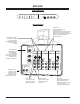
50/60” Wiring Diagram - Front PFS , PFT PFS PFC PFS PFC PFT PFS PFT CONTROL SUB P.W.B. from TERMINAL P.W.B. from SIGNAL P.W.B. CONTROL P.W.B. VM SUB P.W.B. LEAD CLAMPER N009 PVMS PVSB from SIGNAL P.W.B. from SIGNAL P.W.B. red(PR) red(PL) PVSG U402 Woofer(L) White - PR PVSR PL blue(PR) brown(PL) from FOCUS PACK Red FOCUS (R) SCREEN (R) + from DEFLECTION P.W.B. PVSR POWER SUPPLY DEF. P.W.B.
” Wiring Diagram - Back Refer to the figure below about the assembly if FOCUS PACK leads. SCREEN (G) (B) (R) PDF2 (B) PSF PR make double loop from SENSOR P.W.B.
65” Wiring Diagram - Back Refer to the figure below about the assembly if FOCUS PACK leads. SCREEN (G) (B) (R) PDF2 (B) PSF PR make double loop from SENSOR P.W.B.
56/65” Wiring Diagram - Front EAS1 PS1 EAS7 EAS3 EAS3 / EAS5 PS1 PS1 PS3 PS1 PDS1 PS3 PS1 PS3 PS1 EAS5 SENSOR P.W.B. PFS , PFT PFS PFC PFS PFC PFT PFS PFT CONTROL SUB P.W.B. from TERMINAL P.W.B. from SIGNAL P.W.B. CONTROL P.W.B. VM SUB P.W.B. LEAD CLAMPER N009 PVMS PVSB from SIGNAL P.W.B. from SIGNAL P.W.B. red(PR) red(PL) PVSG U402 Woofer(L) White - PR PVSR PL blue(PR) brown(PL) from FOCUS PACK Red FOCUS (R) SCREEN (R) + from DEFLECTION P.W.B. PVSR POWER SUPPLY DEF.
SECTION 6 1 Convergence Circuit 1/2 2 3 4 5 6 7 8 G F E D C CRITICAL SAFETY COMPONENTS ARE IDENTIFIED BY THE SYMBOL REPLACE ONLY WITH PART NUMBERS SPECIFIED. . 6-1 NOTE: WAVEFORMS AND VOLTAGES WERE MEASURED AT 120VAC, CHANNEL 5, AND NSTC COLOR BARS.
Convergence Circuit 2/2 1 2 3 4 5 6 7 8 G F E D C CRITICAL SAFETY COMPONENTS ARE IDENTIFIED BY THE SYMBOL REPLACE ONLY WITH PART NUMBERS SPECIFIED. . 6-2 NOTE: WAVEFORMS AND VOLTAGES WERE MEASURED AT 120VAC, CHANNEL 5, AND NSTC COLOR BARS.
Magic Focus Circuit 1 2 3 4 5 6 7 8 G F E D C CRITICAL SAFETY COMPONENTS ARE IDENTIFIED BY THE SYMBOL REPLACE ONLY WITH PART NUMBERS SPECIFIED. . 6-3 NOTE: WAVEFORMS AND VOLTAGES WERE MEASURED AT 120VAC, CHANNEL 5, AND NSTC COLOR BARS.
Deflection Power Supply Circuit 1 2 3 4 5 6 7 8 G F E D C CRITICAL SAFETY COMPONENTS ARE IDENTIFIED BY THE SYMBOL REPLACE ONLY WITH PART NUMBERS SPECIFIED. . 6-4 NOTE: WAVEFORMS AND VOLTAGES WERE MEASURED AT 120VAC, CHANNEL 5, AND NSTC COLOR BARS.
Deflection Circuit 1 2 3 4 5 6 7 8 G F E D C CRITICAL SAFETY COMPONENTS ARE IDENTIFIED BY THE SYMBOL REPLACE ONLY WITH PART NUMBERS SPECIFIED. . 6-5 NOTE: WAVEFORMS AND VOLTAGES WERE MEASURED AT 120VAC, CHANNEL 5, AND NSTC COLOR BARS.
Power Supply Circuit 1 2 3 4 5 6 7 8 G F E D C CRITICAL SAFETY COMPONENTS ARE IDENTIFIED BY THE SYMBOL REPLACE ONLY WITH PART NUMBERS SPECIFIED. . 6-6 NOTE: WAVEFORMS AND VOLTAGES WERE MEASURED AT 120VAC, CHANNEL 5, AND NSTC COLOR BARS.
Signal Circuit 1/4 1 2 3 4 5 6 7 8 G F E D C CRITICAL SAFETY COMPONENTS ARE IDENTIFIED BY THE SYMBOL REPLACE ONLY WITH PART NUMBERS SPECIFIED. . 6-7 NOTE: WAVEFORMS AND VOLTAGES WERE MEASURED AT 120VAC, CHANNEL 5, AND NSTC COLOR BARS.
Signal Circuit 2/4 1 2 3 4 5 6 7 8 G F E D C CRITICAL SAFETY COMPONENTS ARE IDENTIFIED BY THE SYMBOL REPLACE ONLY WITH PART NUMBERS SPECIFIED. . 6-8 NOTE: WAVEFORMS AND VOLTAGES WERE MEASURED AT 120VAC, CHANNEL 5, AND NSTC COLOR BARS.
Signal Circuit 3/4 1 2 3 4 5 6 7 8 G F E D C CRITICAL SAFETY COMPONENTS ARE IDENTIFIED BY THE SYMBOL REPLACE ONLY WITH PART NUMBERS SPECIFIED. . 6-9 NOTE: WAVEFORMS AND VOLTAGES WERE MEASURED AT 120VAC, CHANNEL 5, AND NSTC COLOR BARS.
Signal Circuit 4/4 1 2 3 4 5 6 7 8 G F E D C CRITICAL SAFETY COMPONENTS ARE IDENTIFIED BY THE SYMBOL REPLACE ONLY WITH PART NUMBERS SPECIFIED. . 6-10 NOTE: WAVEFORMS AND VOLTAGES WERE MEASURED AT 120VAC, CHANNEL 5, AND NSTC COLOR BARS.
SRS Circuit 1 2 3 4 5 6 7 8 G F E D C CRITICAL SAFETY COMPONENTS ARE IDENTIFIED BY THE SYMBOL REPLACE ONLY WITH PART NUMBERS SPECIFIED. . 6-11 NOTE: WAVEFORMS AND VOLTAGES WERE MEASURED AT 120VAC, CHANNEL 5, AND NSTC COLOR BARS.
Velocity Modulator Circuit 1 2 3 4 5 6 7 8 G F E D C CRITICAL SAFETY COMPONENTS ARE IDENTIFIED BY THE SYMBOL REPLACE ONLY WITH PART NUMBERS SPECIFIED. . 6-12 NOTE: WAVEFORMS AND VOLTAGES WERE MEASURED AT 120VAC, CHANNEL 5, AND NSTC COLOR BARS.