
Manual


Installing the Z-Point
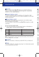
Place the Z-Point with the side with the push-button for the spring clamp
against the rail so that the rear edge of the housing (Fig. 3/E) fits into a
transverse groove on the rail.
Press the push-button (Fig. 4/F) and at the same time guide the Z-Point in the
direction of the arrow (Fig. 4) over the rail until the Z-Point clearly locks into
position on the rail.
Removing the Z-Point from the rail
Follow the above directions but in the reverse order – press the push button
for the spring clamp and move the Z-Point in the opposite direction to the
arrow (Fig. 4).
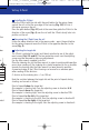
Adjusting the target dot
The Z-Point is adjusted for height and lateral variation by use of the adjust-
ment screws (Fig. 2/G and H). The two protective covers over the adjusting
screws must be removed to make any adjustments.
Use the Allen wrench supplied to do this.
Place the indexing disc on the Allen wrench. In order to avoid possible parallax
errors when reading off, the indexing disc should be pushed as far as possible
towards the housing after the Allen wrench has been placed in position.
A prominent edge of the Z-Point housing can be used as a reference point
when reading off the divisions.
(1 division on the indexing disc = 1 cm/100 m).
Note the variation between the target dot and the point of impact during
shooting and correct as follows:
Point of impact below the target dot
(the weapon is shooting low): turn the adjusting screw in direction H/U
Point of impact above the target dot
(the weapon is shooting high): turn the adjusting screw in direction T/D
Point of impact to the left of the target dot
(the weapon is shooting to the left): turn the adjusting screw in direction R
Point of impact to the right of the target dot
(the weapon is shooting to the right): turn the adjusting screw in direction L
602950_ZEISS GBH_02 Victory_Z-Point_Innen/S. 7/Cyan = Pantone Reflex Blue/Schwarz
s/her
-
mber
is
that
ail.
unted
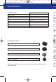
Victory Z-Point
02 Vict_Z-Point_innen_pan.qxd4 03.01.2007 15:47 Uhr Seite