Axiovert 25 / 25 C / 25 CFL Inverted Microscope Operating Manual
Carl Zeiss Axiovert 25, Axiovert 25 C, Axiovert 25 CFL Knowledge of this manual is required for the operation of the instrument. Would you therefore please make yourself familiar with the contents of this manual and pay special attention to hints concerning the safe operation of the instrument. The specifications are subject to change; the manual is not covered by an update service.
1%)/!+- 1%)/!+- 1%)/!+- TABLE OF CONTENTS #! %-&! * #! )*2+%#$ &! )" )(-!(-, %,- )" "%#.
7(.5$13 7(.5$13 7(.5$13 &$ 22$,!+8 .% 3'$ (-2314,$-3 9 -/ "*(-& 9 -23 ++ 3(.
2&+0",. 2&+0",. 2&+0",. $" 3 MAINTENANCE AND TROUBLESHOOTING &*."* * " 5 ,+/ ("-%++.&*$ *! -",0& " 5 ANNEX &-. +# '"3 1+,!- 5 &-. +# ,"0& .
6(.4$02 6(.4$02 6(.4$02 &$ (&30$ 9 (- ,.#3+$1 .% 2'$ 6(.4$02 -# 6(.4$02 ,.#$+1 9 (&30$ 9 /2(" + #$1(&- .% 2'$ 6(.4$02 9 (&30$ 9 8 8 6(.4$02 ".-%(&30 2(.-1 9 (&30$ 9 8 8 6(.4$02 ".-%(&30 2(.
7)/5%13 7)/5%13 7)/5%13 !'% )'41% : #/.31!23 6)3( -)#1/3)3%1 0,!3%2 : )'41% : 40), )-!'%2 6)3( #/.31!23 : )'41% : !19 9 9 9 !1 2,)$%1 : )'41% : "2%15!3)/. 4.$%1 1%&,%#3%$ ,)'(3 &,4/1%2#%.
/!'- )+ /!'- )+ /!'- )+ • ! ,) * !&+ ) + !& + + /+ ) &,% ) & (+!'& ! ,) 4 ') / %($ ) )* +' ! ,) ' !& * +!'& ') !+ %* % &+!'& !& + + /+ *$ * & & !+ % &,% ) ) ') / %($ 1 0 (! +, 4 2 2 % &* + + + 0 (! +, !& ! ,) !& * +!'&3 !* % )# .
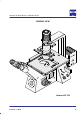
GENERAL VIEW Axiovert 25 CFL
Axiovert 25, Axiovert 25 C, Axiovert 25 CFL The Axiovert 25 microscopes and their original accessories may be used only for the microscopy techniques described in this manual. The manufacturer cannot take liability for any other application, including that of individual modules or components. This also applies to all servicing and repair work which has not been performed by authorized service personnel.
3$*1 -/ 3$*1 -/ 3$*1 -/ # ) /# ($ -*. *+ . # 1 ) *)) / /* /# '$) *)) /$)" ' (+. $).$ /# $)./-0( )/ ( 4 *)/ $) )" -*0. 1*'/ " ) /# *+ )$)" *! *1 -. *- /# - (*1 ' *! *(+*) )/. $! )*/ - ,0$- !*- !0) /$*) ( 4 3+*. *(+*) )/. *)/ $)$)" )" -*0. 1*'/ " # - !*- /# $)./-0( )/ (0./ $. *)) / !-*( /# '$) !*- $/ $. *+ ) !* %0./( )/ # )" *! *(+*) )/. ( $)/ ) ) *- - + $- ! %0./( )/ ( $)/ ) ) *- - + $- *! /# '$1 $).
Axiovert 25, Axiovert 25 C, Axiovert 25 CFL 1 Description 1.
Axiovert 25, Axiovert 25 C, Axiovert 25 CFL Major instrument features are: • Modular design for the optimum performance of application tasks • Stand featuring a compact design, high operating convenience thanks to a stage height of only 188 mm and lowĆmounted controls • Integrated 6 V, 30 W power supply • Continuous sly variable illuminance • Upright, uninverted images • Fixed Köhler illumination, changeable condenser, numeric apertures of 0.55, 0.4 or 0.
.!&, (* .!&, (* .!&, (* 1.2.1 Mechanical design Axiovert 25 • *+(!% % !%* ( * -! ( % '&- ( )+''#/ &( !##+$!% *!&% -!* &+* * % &( * ,&#* *& % * * !%)*(+$ %* • &( &% %) ( ( '# # % $&, # • *+(!% & .! # & () % !% (!, -!* & +)!% *!% &% * # %) *+(( * • !%& +# ( *+ "+)* # *& *-& ! *) -!* &% !.
Axiovert 25, Axiovert 25 C, Axiovert 25 CFL 1.2.2 Optical design (shown using the example of the Axiovert 25 CFL) The timeĆtried ICS optics (Infinity ColourĆcorrected System) guarantee high optical performance for all methods (up to field number 20, tube factor 1x). Different combinations of lenses and eyepieces allow optimum performance of the intended application. Depending on the configuration, the Axiovert 25 microscopes are equipped with a 6 V, 30 W halogen lamp and an HBO 50.
Axiovert 25, Axiovert 25 C, Axiovert 25 CFL 1.3 Technical data (1) Dimensions and weight Dimensions (width x depth x height) Axiovert 25 . . . . . . . . . . . . . . . . . . . . . . . . . . . . . . . . . . . . . . . . . . . . . . . . . . . . . . . . . 245 x 570 x 510 mm Axiovert 25 C . . . . . . . . . . . . . . . . . . . . . . . . . . . . . . . . . . . . . . . . . . . . . . . . . . . . . . . 245 x 570 x 510 mm Axiovert 25 CFL . . . . . . . . . . . . . . . . . . . . . . . . . . . . . . . . . . . . . . . .
Axiovert 25, Axiovert 25 C, Axiovert 25 CFL Line voltage . . . . . . . . . . . . . . . . . . . . . . . . . . . . . . . . . . . . . . . . . . . . . . . . . . . . . . . . . 100 ... 240 V AC ±10 % Line frequency . . . . . . . . . . . . . . . . . . . . . . . . . . . . . . . . . . . . . . . . . . . . . . . . . . . . . . . . . . . . . . . . . . . 50ā/ā60 Hz Label of voltage range . . . . . . . . . . . . . . . . . . . . . . . . . . . . . . . . . . . . . . . . . . . . . . . . . . . . . .
Axiovert 25, Axiovert 25 C, Axiovert 25 CFL Objectives . . . . . . . . . . . . . . . . . . . . . . . . . . . . . . . . . . . . . . . . . . . . . . . . . . . . . . . ICS line of objectives with W 0.8" x 1ā/ā36 thread Objective change . . . . . . . . . . . . . . . . . . . . . . . . . . . . . . . . . . . . . . . . . . . . . . manual via 5Ćfold lens turret Eyepieces . . . . . . . . . . . . . . . . . . . . . . . . . . . . . . . . . . . . . . . . . . . . . . . . . . . . . . . .
Axiovert 25, Axiovert 25 C, Axiovert 25 CFL 1.4 Overview of components 1.4.1 Microscope configurations Microscope configurations, transmitted and re reĆ fl t d light flected li ht Order No. 1.1 1.2 1.3 Axiovert 25 microscope stand Axiovert 25 C microscope stand Axiovert 25 CFL microscope stand 451200 451205 451210 x 2 Halogen lamp, 6 V, 30 W 000000Ć0402Ć943 x 3.1 3.2 3.3 0.2 condenser 0.4 condenser 0.55 condenser 451236 451235 451237 x 4.1 4.2 4.
* #) %' * #) %' * #) %' Microscope configurations, transmitted and reĆ flected light + $ & + $ ! *, , % + $ ! *, , % # #") %& #" !' % ('% !- "& '+ !' % (&' #) % #% * #) %' - * * Order No.
Specimen guide M Specimen stage, 210 x 290 mm Halogen lamp, 6 V, 30 W Holding frame M for microtiter plate 96 positions Ph0Ć0.2 ring diaphragm Ph1Ć0.2 ring diaphragm 0.2 condenser CPĆAchromat 5x/0,12 Ph0 CPĆAchromat 10x/0,25 Ph1 LDĆAchrostigmat 20x/0,30 Ph1 Eyepiece Pl 10x/18 spect. foc.
Dust cover Halogen lamp, 6 V, 30 W Conversion filter CB12, d = 32x2 NeutralĆdensity filter N = 0.06, d = 32x2 Ph0Ć0.4 ring diagraphm Ph1Ć0.4 ring diagraphm Ph2Ć0.4 ring diagraphm Ph/H/Ph slider 0.4 condenser 2x Eyepiece Pl 10x/18 spect. foc.
# " # " # " Power supply unit for HBO 50 220/240 V, 50Ć60 Hz, 350 VA StepĆdown transformer for 1200 VA with mains cable with American flat plug ! Halogen lamp, 6 V, 30 W Lamp housing HBO 50 with aspherical collector ! 2x Eyepiece Pl 10x/18 spect. foc.
Axiovert 25, Axiovert 25 C, Axiovert 25 CFL 1.4.2 Accessories for the microscope configurations Accessories for microscope configurations Order No. Configuration 491205 9804 491206 9804 491207 9804 1 Specimen guide M for Axiovert 25 451230 x d d 2 2.1 2.2 2.3 2.4 2.5 2.6 2.7 2.8 2.9 2.10 Holding frame for specimen guide M for Specimen mount 76 x 26 Microtest plates 60, 72 and 120 pos. Microtiter plates 96 pos. Multiple dishes (133.5x88.
Axiovert 25, Axiovert 25 C, Axiovert 25 CFL Accessories for microscope configurations Order No. Configuration 491205 9804 491206 9804 491207 9804 x x x x d d x x x x x x x x x x x d x x x x x x x x x d d x x x x x 451245 451246 451247 x x x x x x x x x 0.2 condenser 0.4 condenser 0.55 condenser 451236 451235 451237 d x x x d x x d x 10.1 10.
Axiovert 25, Axiovert 25 C, Axiovert 25 CFL Accessories for microscope configurations Order No. Configuration 491205 9804 491206 9804 491207 9804 440146 440850 440851 440154 440155 440158 444930 444931 x x x x x x x x x x x x x x x x x x x x d x x x 444231 9901 444232 9902 444232 0206 444053 444054 444801 x x x x x x x x x x x x x 12.17 12.18 12.19 12.20 12.21 12.22 12.23 12.24 LDĆAchrostigmat 32xā/ā0.35 Ph1 Var1 LDĆAchroplan 32xā/ā0.40 LDĆAchroplan 32xā/ā0.40 Ph2 LDĆAchrostigmat 40xā/ā0.
" " " Specimen guide M Holding frame M for Specimen mount 76x26 Microtest plates 60, 72 und 120 pos. Petri dishes d = 36 mm Video adapter ENG 1/2" 0.5x Petri dishes d = 54 mm Petri dishes d = 65 mm Video adapter C 1/2" 0.5x Petri dishes d = 88 mm Videozoom adapter C 1/3" 0,32x Ć 0,8x Microtitre plates 96 pos. 2.5x/T2 photo adapter Multiple dishes 133.5x88.
Eyepieces EĆPl 10x/20 Br. EĆPl 10x/20 Br. foc. with Diaphragm part, screwĆin Pl 16x/16 Br. Pl 16x/16 Br. foc. NeutralĆdensity, interference and conversion filter d = 32 in accordance with valid price list 0.2 condenser 0.55 condenser Objectives and cover glass caps as detailed in Section 1.4.2 0.
Axiovert 25, Axiovert 25 C, Axiovert 25 CFL 1.5 Function elements (see Figures 1Ć5, 1Ć6 and 1Ć7 following the table) Item No. Designation Purposeā/ādescription ă1 ă2 Microscope stand Auxiliary microscope ă3 Diaphragm part, screwĆin ă4 Eyepiece, focusing ă5 Binocular tube swivelling ă6 ă7 Eyepiece Monocular ă8 ă9 Specimen guide M coaxial drive Specimen stage 10 11 Aperture diaphragm Phā/āHā/āPh slider 12 13 14 15 0.4 condenser Condenser change position 0.2 or 0.
Axiovert 25, Axiovert 25 C, Axiovert 25 CFL Item No. Designation Purposeā/ādescription 18b Varā/āHā/āVar slider Slider for VAREL contrast, left and right position each accept one VAREL stop, center position with dia.
18b 14 16 15 18a 17 13 12 10 7 8 6 11 9 5 4 3 1 2 28 27 25 23 31 36 35 34 37 Figure 1Ć5 Function elements of the Axiovert 25
18b 14 16 15 17 18a 13 12 10 11 7 6 8 9 5 4 3 1 2 33 36 35 31 30 28 27 25 23 32 34 37 Figure 1Ć6 Function elements of the Axiovert 25 C
14 18b 16 15 17 18a 13 12 7 10 8 6 19 11 9 5 21 20 22 4 3 2 31 1 33 36 30 29 28 27 25 26 24 23 32 35 34 37 Figure 1Ć7 Function elements of the Axiovert 25 CFL
Axiovert 25, Axiovert 25 C, Axiovert 25 CFL 2 Operation 2.1 Assembly of the instrument 2.1.1 Unpacking The various models of the Axiovert 25 microscope, including accessories, are delivered in commercially available packaging. It is recommended to keep the transport containers in case the instrument must be stored for a long period of time or returned to the manufacturer. • Open the packaging. • Remove the cardboard box (2Ć1/1) containing the accessories.
Axiovert 25, Axiovert 25 C, Axiovert 25 CFL 2.1.2 Installation (1) Preparations • Place the microscope stand on a suitable work surface. 2 3 1 • Remove the plastic sleeve (2Ć2ā/ā1). • Remove the foam part (2Ć2ā/ā2) which secures the condenser slider. • Remove the foam part (2Ć3ā/ā1) above the nosepiece. NOTE Figure 2Ć2 The filter slider (2Ć2ā/ā3) is firmly integrated; the suitable filters (green filter, attenuation filter) are not inserted during transport.
Axiovert 25, Axiovert 25 C, Axiovert 25 CFL (3) Insertion of ring diaphragm sliders • Remove the dust protection slider (2Ć4ā/ā1) from the slider mount and replace it with the 1 - Phā/āHā/āPh slider (2Ć4ā/ā2) or the - Phā/āHā/āVar slider (2Ć4ā/ā3); clickstop the slider in the center position (brightfield position). 2 NOTE The marking on the slider must be legible upright and the inserted ring diaphragms must correspond to the condenserā/ālens combination (also see the table on page 2Ć13).
Axiovert 25, Axiovert 25 C, Axiovert 25 CFL (5) Attachment of the specimen guide M • Attach the specimen guide M for Axiovert 25 (2Ć6ā/ā6) to the left or right of the stage (2Ć6ā/ā2) and secure it from below with three knurled screws (2Ć6ā/ā3). 1 NOTE 2 7 6 5 4 Figure 2Ć6 NOTE 3 The L rail (2Ć6ā/ā4) of the specimen guide must be flush with the stage. The specimen guide is moved by means of a coaxial drive (2Ć6ā/ā5) (bottom drive knob for X movement and top drive knob for Y movement).
Axiovert 25, Axiovert 25 C, Axiovert 25 CFL (6) Connection to the line IMPORTANT Check whether the voltage indicated on the instrument rear complies with the line voltage! • Connect line cable (2Ć7/4) to the instrument socket and the line. • Switch on the instrument via the On/Off switch (2Ć7/3) on the right of the instrument. NOTE When the instrument is switched off, the "0" marking is visible on the line switch. • The instrument is ready for operation when the pilot lamp is on.
Axiovert 25, Axiovert 25 C, Axiovert 25 CFL 1 2 (7) Inserting the eyepieces • Remove the dust covers (2Ć8/1) and insert the fixed eyepieces (2Ć8/2, 3) and the focusing eyepieces in the eyepiece tube (2Ć8/4). NOTE 4 Figure 2Ć8 3 Depending on the configuration, one or two eyepieces may permit focusing to compensate for differing degrees of myopia of the two eyes.
Axiovert 25, Axiovert 25 C, Axiovert 25 CFL (9) Using the binocular tube • The eyepiece distance is matched to the indiĆ vidual interpupillary distance by swinging the eyepiece tubes symmetrically towards one another. • A higher (2Ć9ā/āA) or lower (2Ć9ā/āB) viewing height is achieved by swiveling the tube. A B (10) Inserting an eyepiece reticle (dia. 26 mm) Figure 2Ć9 Positions of the binocular tube • The WĆPl eyepieces 10x/18 foc. are intended for use with reticles.
Axiovert 25, Axiovert 25 C, Axiovert 25 CFL (11) āPositioning/switching on the instrument 3 • Unless already done, switch on the instrument using the On/Off switch (2Ć11ā/ā5). 4 • After switching on, the lamp in the illuminaĆ tor (2Ć11/4) must light up. 2 1 • Set the required brightness illumination control (2Ć11ā/ā6). via the • If required, insert attenuation filter or green filter (2Ć11/3) in the beam path via the filter slider (2Ć11ā/ā2). 7 Figure 2Ć11 2.
Axiovert 25, Axiovert 25 C, Axiovert 25 CFL 2.3 Use of LD objectives When inverted microscopes are used for analyses, the bottom thickness of the vessels used differs considerably from the standard cover slip thickness of 0.17 mm. Normally, such distances are easily bridged by the working distances of lowĆpower objectives: - CP Achromat 5x/0.12 FWD (in air) 10.8 mm or - CP Achromat 10x/0.25 FWD (in air) 5.1 mm.
Axiovert 25, Axiovert 25 C, Axiovert 25 CFL 2.4 Illumination and contrasting techniques The description/application of illumination/contrasting techniques is based on the following microscope settings: • Axiovert 25 microscope is switched on. • The "Illuminance" control (1Ć6ā/ā25) is in center position. • The "beam path" switch (1Ć6ā/ā30) is in the position for observation. 2.4.1 Use of condensers Condenser Free distance between condenser and stage surface Objective magnification Technique 0.2 0.
Axiovert 25, Axiovert 25 C, Axiovert 25 CFL Height adjustment of the condenser 0.55 The height of the condenser 0.55 can be adjusted in order to obtain homogeneous illumination of the object field and optimum intensities in all the focusing positions of the objective. When the fixation screw has been loosened, the lower part of the condenser can be moved in the direction of the upper part and clamped in any position.
Axiovert 25, Axiovert 25 C, Axiovert 25 CFL 2.4.3 Phase contrast • Preparations as described in section 2.4 and 2.4.1. NOTE 1 PhaseĆcontrast objectives labeled in green. are • Swing phaseĆcontrast objective (2Ć15/3) in the beam path. 4 2 3 • Open the aperture diaphragm (2Ć15ā/ā2) entirely. • Insert the auxiliary lens (2Ć15/4) in one of the tubes instead of an eyepiece and make the phase rings of the objective visible by focusing the eyelens.
Axiovert 25, Axiovert 25 C, Axiovert 25 CFL NOTE Should the setting range of the centering screws not be sufficient, please check whether the condenser is at the front stop and the Ph/H/Ph slider has engaged. Exact imaging of the annular diaphragm requires a planeĆparallel object. • Replace the auxiliary lens with the eyepiece again.
Axiovert 25, Axiovert 25 C, Axiovert 25 CFL 2.4.4 VAREL contrast VAREL contrast provides a reliefĆlike image of specimens and can be used as an alternative to phase contrast. VAREL contrast can also be used on curved surfaces, e.g. 96 microtiter plates, for which no contrast can be achieved with phase contrast (no flush ring positioning!). • Preparations as described in section 2.4 and 2.4.1. • Open the aperture diaphragm (2Ć18ā/ā1) completely.
Axiovert 25, Axiovert 25 C, Axiovert 25 CFL • Shifting the VAREL illumination to outside the pupil corresponds to oneĆsided darkfield illumination. NOTE • Shifting the VAREL illumination between the Ph and VAREL rings of the objective corresponds to inclined brightfield illumination. • The middle engaging position of the Phā/āHā/āVar slider permits brightfield illumination. • The left engaging position of the Phā/āHā/āVar slider permits the fast change from VAREL to Ph contrast.
Axiovert 25, Axiovert 25 C, Axiovert 25 CFL 2.4.5 Reflected light fluorescence requires the use of the Axiovert 25 CFL microscope stand. • Select a point on the specimen in transmitted light brightfield or phase contrast. To do this, switch the reflector mount (2Ć22ā/ā10) to free passage, switch on the halogen lamp (2Ć22ā/ā2) and move the phase slider (2Ć22ā/ā3) to the middle position (brightfield) or to the position with the ring diaphragm (phase contrast).
Axiovert 25, Axiovert 25 C, Axiovert 25 CFL 2.5 Working with the specimen guide M and holding frames • Preparations as described in section 2.4 and 2.4.1. 1 • Attach specimen guide M as described in section 2.1.2(5). In conjunction with various holding frames (2Ć23ā/ā3), e.g. for 76 x 26 mm specimen mounts (2Ć23ā/ā2), the specimen guide M (2Ć23ā/ā6) offers the possibility of sensitive movement by means of a coaxial drive (2Ć23ā/ā4).
Figure 2Ć24 1 2 3 4 5 6 Selection of available holding frames
Axiovert 25, Axiovert 25 C, Axiovert 25 CFL 2.6 Using the focusing eyepiece Measuring and counting plates or photo reticles are needed for microscopic measuring and counting. A small selection is shown below: 0 1 2 3 4 5 6 7 8 9 10 11 12 13 14 0 1 2 3 4 5 6 7 8 9 10 11 12 13 14 Photo reticle MC 10xā/ād = 26 Reticle micrometer 14:140ā/ād = 26 Order No. 454075 Graduation length = 14 mm Increments = 0.1 mm Graduation error 0.001 mm Order No.
Axiovert 25, Axiovert 25 C, Axiovert 25 CFL 2.7 Working with micromanipulators The Axiovert microscopes are prepared as follows for the attachment of micromanipulators: • Three M4 threaded holes (2Ć26ā/ā1) on the left and right underside of the stage. • Three M5 threaded holes (2Ć26ā/ā2) on the left and right sides of the stand. • Four M5 threaded holes (2Ć26ā/ā3) on the underside of the stand for securing the stand.
+ $) %' 2.
Axiovert 25, Axiovert 25 C, Axiovert 25 CFL 2.8.1 Glass stage 1 2 The glass stage (2Ć28ā/ā3) enables convenient working with simultaneous observation of the objectives and easily meets the high demands on cleanliness. Installation • Fit the glass stage onto the stage coupling point using the spacers. 3 • Secure the glass stage on the stand using the securing screws (2Ć28ā/ā2). • Seal the rear holes on the surface of the glass stage by means of the cover (2Ć28ā/ā1).
Axiovert 25, Axiovert 25 C, Axiovert 25 CFL 2.9 Documentation 2.9.1 Photomicrography The Axiovert 25 C and 25 CFL microscopes can be changed from observation to photomicrography by switching the beam path. Since this is a 100% changeover, simultaneous observation and photography is not possible. The 2.5x/T2 camera adapter allows commercially available 35 mm cameras to be attached to the microscope. • Remove dust cover (2Ć29/2) or camera lens from the camera housing (2Ć29/1).
Axiovert 25, Axiovert 25 C, Axiovert 25 CFL • Switch on the microscope; when using color film (artificial light), set the "illuminance" control (2Ć29/11) to maximum brightness (right stop position: 3200 K) and use an attenuation filter if required. • Select the object detail to be photographed via the binocular tube. NOTE To determine the image section and for the precise focusing of the image, the focusing eyepiece must be equipped with the photo reticle MC 10x/dia. 26 (see section 2.6).
Axiovert 25, Axiovert 25 C, Axiovert 25 CFL 3 Maintenance and troubleshooting 3.1 Maintenance Maintenance of the the Axiovert 25 microscope is limited to the following operations: • Cover the instrument with the dust cover after every use. • Clean exposed optical components whenever required. • Carefully remove moisture deposit or precipitated aggressive vapor using a dry cloth. • Protect the instrument from temperatures above 50 °C, frost, humidity, chemically aggressive vapor/substances.
Axiovert 25, Axiovert 25 C, Axiovert 25 CFL 3.2 Troubleshooting and service Troubleshooting on the Axiovert 25 is limited to only a few actions: • Check the line voltage • Checking the illumination equipment - Change of fuses as described under (1) - Change of halogen lamp as described under (2) - Change of HBO 50 lamp as described under (3) - Change of reflector as described under (4) (1) Checking the line voltage • Check the line cable (3Ć1/3) and replace it, if necessary.
Axiovert 25, Axiovert 25 C, Axiovert 25 CFL (2) Change of halogen lamp Proceed as follows to change the lamp: • Disconnect the instrument from the line. • Unlock the housing (3Ć2/1) by slightly turning it counterclockwise and remove it. • Remove the halogen lamp with adjustment base (3Ć2/2) after a cooling time of approx. 15Ăminutes.
Axiovert 25, Axiovert 25 C, Axiovert 25 CFL (3) Change of HBO 50 lamp The HBO 50 illuminator is used for reflected light fluorescence excitation.
Axiovert 25, Axiovert 25 C, Axiovert 25 CFL Safety notes for use CAUTION The HBO 50 is under high pressure during operation. It may therefore only be operated in a closed microscope illuminator. • The cooling process of the lamp housing must not be obstructed by covers. • The HBO 50 must cool down for approx. 15 minutes before the lamp can be changed. • The lamp emits UV radiation during operation. Protect your eyes and skin from this radiation.
Axiovert 25, Axiovert 25 C, Axiovert 25 CFL • Use the SW 3 screwdriver to loosen the clamping screw on the heatsink and remove the used lamp. The cable on the heatsink must not be removed. • Hold the new lamp on the marked metal base and insert it in the heatsink in such a way that its reflecting part is at the bottom when inserted in the mount. The reflecting meltĆoff part of the lamp must point to the side (to avoid interference with the image).
Axiovert 25, Axiovert 25 C, Axiovert 25 CFL Lamp adjustment CAUTION Never look directly into the ignited lamp in order to avoid (irreparable) damage to your eyes. Use protective eyewear, e.g. sunĆ glasses, to protect your eyes when observing the bright light spot. • Unscrew an objective and check the image of the light source via the empty opening on a piece of paper in the object plane (on the object stage).
Axiovert 25, Axiovert 25 C, Axiovert 25 CFL (4) Change of reflectors Fl The reflectors are equipped in the factory with the appropriate filter sets consisting of excitation filter, dichroic beam splitter and barrier filter. However, it is possible to allow the use of any required Fl filter set.
A Change of fluorescence reflector 1 2 3 4 5 6 9 10 6 6 8 7 11 12 13 8 B Change of fluorescence filter 7 Figure 3Ć7 Operating the Fl reflector module
+ ") %' + ") %' + ") %' % # %& " ! "#' "% '%"! " #"! !'& !& ' !&'%( !' ! " ' '% . " #"! !'& " ' + ") %' , "! , # % "% , % && & %) &' "% &# , # %&"!! " !&(% ' "#' ( & '' ! ! '%"( .
( "& #% ( "& #% ( "& #% • $% " ) '"# $ • $% " # & % "!$ • #% % "! ! "# ! ' % * * * * • "! "# %) # % "! + +
Axiovert 25, Axiovert 25 C, Axiovert 25 CFL List of key words Page A Accessories . . . . . . . . . . . . . . . . . . . . . . . . . . . . . . . . . . . . . . . . . . . . . . . . . . . . . . . . . . . . . . . . 1Ć13 Ambient conditions . . . . . . . . . . . . . . . . . . . . . . . . . . . . . . . . . . . . . . . . . . . . . . . . . . . . . . . . 1Ć5 Assembly . . . . . . . . . . . . . . . . . . . . . . . . . . . . . . . . . . . . . . . . . . . . . . . . . . . . . . . . . . . . . . . . .
Axiovert 25, Axiovert 25 C, Axiovert 25 CFL Page Filter sets . . . . . . . . . . . . . . . . . . . . . . . . . . . . . . . . . . . . . . . . . . . . . . . . . . . . . . . . . . . . . . . . . Fluorescence filter replacement . . . . . . . . . . . . . . . . . . . . . . . . . . . . . . . . . . . . . . . . . . . . . Fluorescence reflector replacement . . . . . . . . . . . . . . . . . . . . . . . . . . . . . . . . . . . . . . . . . Free operating distances . . . . . . . . . . . . . . . . . . . . . . . . . . .
Axiovert 25, Axiovert 25 C, Axiovert 25 CFL Page Main assemblies . . . . . . . . . . . . . . . . . . . . . . . . . . . . . . . . . . . . . . . . . . . . . . . . . . . . . . . . . . . Maintenance . . . . . . . . . . . . . . . . . . . . . . . . . . . . . . . . . . . . . . . . . . . . . . . . . . . . . . . . . . . . . . Mass . . . . . . . . . . . . . . . . . . . . . . . . . . . . . . . . . . . . . . . . . . . . . . . . . . . . . . . . . . . . . . . . . . . . . Measuring plates . . . . . . . . . . . . . . .
Axiovert 25, Axiovert 25 C, Axiovert 25 CFL Page Service . . . . . . . . . . . . . . . . . . . . . . . . . . . . . . . . . . . . . . . . . . . . . . . . . . . . . . . . . . . . . . . . . . . . Specimen guide . . . . . . . . . . . . . . . . . . . . . . . . . . . . . . . . . . . . . . . . . . . . . . . . . . . . . . . . . . . Stage replacement . . . . . . . . . . . . . . . . . . . . . . . . . . . . . . . . . . . . . . . . . . . . . . . . . . . . . . . . . StartĆup . . . . . . . . . . . . . . . . . . . . .
Axiovert 25, Axiovert 25 C, Axiovert 25 CFL BP Bandpass Br. Spectacle wearer C Camera CB Conversion Blue Corr corrected CP Clinical Plan D Cover glass thickness DF Dark field DIN German standards institute EG European Community EN European standard ENG Electronic News Gathering FWD Free working distance Fl Fluorescence foc.