Zebra R2844-Z ® Smart Label Printer and Encoder User Guide Part #980476-001 | Rev.
ii 980476-001A
Proprietary Statement This manual contains proprietary information of the manufacturer. It is intended solely for the information and use of parties operating and maintaining the equipment described herein. Such proprietary information may not be used, reproduced, or disclosed to any other parties for any other purpose without the expressed written permission of the manufacturer. Product Improvements Continuous improvement of products is a policy of the manufacturer.
Battery The main printed circuit board assembly includes a three-volt lithium battery. CAUTION • Risk of explosion if battery is replaced with an incorrect type. Note • Recycle batteries according to local your guidelines and regulations. Shock Hazard The printer and power supply should never be operated in a location where either one can get wet. Personal injury could result. Media and Ribbon Always use high-quality, approved labels, tags and ribbons.
Contents Introduction Hello!. . . . . . . . . . . . . . . . . . . . . . . . . . . . . . . . . . . . . . . . . . . . . . . . . . . . . What's in the Box?. . . . . . . . . . . . . . . . . . . . . . . . . . . . . . . . . . . . . . . . . . . Inspecting the Printer. . . . . . . . . . . . . . . . . . . . . . . . . . . . . . . . . . . . . . . . . Opening the printer . . . . . . . . . . . . . . . . . . . . . . . . . . . . . . . . . . . . . . . Closing the printer. . . . . . . . . . . . . . . . . . . . . . . . . . .
Communicating with the Printer . . . . . . . . . . . . . . . . . . . . . . . . . . . . . . . 18 Universal Serial Bus (USB) Communications . . . . . . . . . . . . . . . . . 18 Parallel Communications . . . . . . . . . . . . . . . . . . . . . . . . . . . . . . . . . 18 Internal Ethernet Communications . . . . . . . . . . . . . . . . . . . . . . . . . . 18 Serial Communications . . . . . . . . . . . . . . . . . . . . . . . . . . . . . . . . . . . 19 Adjusting the Print Width . . . . . . . . . . . . . . . . . .
Troubleshooting Resolutions . . . . . . . . . . . . . . . . . . . . . . . . . . . . . . . . . . . . . . . . . . . . . . . 61 Print Quality Problems . . . . . . . . . . . . . . . . . . . . . . . . . . . . . . . . . . . . . . 64 RFID Symptoms . . . . . . . . . . . . . . . . . . . . . . . . . . . . . . . . . . . . . . . . . . . 66 External reader cannot confirm RFID tags are programmed. . . . . . . 66 VOID messages are printed across media. . . . . . . . . . . . . . . . . . . . . 66 Nothing is printed. . . . .
980476-001A
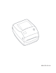
Introduction This section describes what you get in your shipping box and provides an overview of printer parts. This section also has procedures that describe how to open and close the printer and report any problems. Hello! ® Thank you for choosing a Zebra R2844-Z™ printer, a high-quality on-demand printer with RFID (radio-frequency identification) capability manufactured by the industry leader in quality, service, and value—Zebra Technologies Corporation.
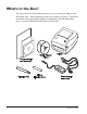
What's in the Box? Save the carton and all packing materials in case you need to ship or store the printer later. After unpacking, make sure you have all parts. Follow the procedures for inspecting the printer to familiarize yourself with printer parts so you can follow the instructions in this book.
Inspecting the Printer Look at the outside of the printer and make sure that all parts are present. Opening the printer To access the media compartment, you must open the printer. Pull the release levers towards you and lift the cover.
INSPECTING THE PRINTER (continued) After opening the printer, check the media compartment.
Closing the printer Hold the top cover and press the “kick-stand” cover lock to release. Lower the top cover. The ribbon carriage automatically folds up into place. Press down until the cover snaps closed.
Reporting Damage If you discover damage or missing parts: ■ Immediately notify and file a damage report with the shipping company. The manufacturer is not responsible for any damage incurred during shipment of the printer and will not cover the repair of this damage under its warranty policy. ■ Keep the carton and all packing material for inspection.
Getting Started This section describes how to set up your printer for the first time and use the most common operating procedures for loading media in tear-off mode and loading ribbon. Modes of Printing You can operate this printer in different modes: ■ Standard tear-off mode allows you to tear off each label (or a strip of labels) after it is printed. ■ In optional peel-off mode, the backing material is peeled away from the label as it is printed. After this label is removed, the next one is printed.
Attaching Power Supply Check the power supply to make certain it is appropriate for your input voltage. Caution • Use the power supply that came with your printer. Never operate the printer and power supply in an area where they can get wet. Serious personal injury could result! 1. Make sure the power switch is in the off position (down). 2. The DC power supply has a barrel connector on one end that must be inserted into the power supply receptacle on the back of the printer. 3.
Loading Roll Media When you load media, you must place the roll on the media hangers and then adjust the media guides. You must use the correct media for the type of printing you require. When printing without a ribbon, you must use direct thermal media. When using ribbon, you must use thermal transfer media. The printer's ribbon sensor detects motion of the supply spindle.
Adjusting the Guides The adjustable guides direct the media toward the platen and print head. 1. Open the media guides by turning the guide adjuster knob to the rear. 2. Thread the media through the guides. 3. Close the media guides by turning the guide adjuster knob to the front. They should just touch, but not restrict, the edges of the media. 4. Unless you need to load ribbon, close the top cover.
Using the Optional Media Adapter Plates If your media roll has a larger diameter core, you can use an accessory to adapt the core to the media holders. 1. Note which position will fit the diameter of the roll core. 2. On the left side plate, align the pegs with the screws and use a small Phillips driver to tighten them. 3. On the right side plate, align the pegs with the screws and use a small Phillips driver to tighten them. 4. Align the plates so that the pegs hold the roll core and press together. 5.
Loading Ribbon You must use thermal transfer media (accepts wax and/or resin transferred off a ribbon) when you use a ribbon. When loading ribbon, you install the supply and take-up rolls, then tighten the ribbon on the carriage. Install the Ribbon Supply Roll Before following these steps, prepare the ribbon by removing its wrapping and pulling its adhesive strip free. 1. Thread the ribbon through the carriage. 2. Press the right side onto the supply hub. 3.
Attach and Tighten the Ribbon You must align the ribbon so that it will be taken straight onto the core. 1. Attach the ribbon to the take up core. Use the adhesive strip on new rolls; otherwise, use tape. 2. Turn the ribbon take-up gear counter-clockwise (top moves toward rear) to remove slack from the ribbon. 3. Close the top cover. Remember that you need to release the cover lock, lower the top cover, and press down until the latches snap into place.
Operator Controls Power Switch Press up to turn ON or down to turn OFF the printer. CAUTION • The power should be turned off before connecting or disconnecting the communications and power cables. Feed Button Press once to feed one blank label. Press once to take the printer out of a “pause” condition. (The printer is put into “pause” by either a programming command or an error condition.) See “What the Status Light is Telling You” on page 61.
Printing a Test Label PRINTER CONFIGURATION Zebra Technologies ZTC R2844-Z-200dpi +10................ +000............... TEAR OFF ........... NON-CONTINUOUS..... WEB................ THERMAL-TRANS...... 104 0/8 MM ......... 1248............... 39.0IN 988MM ..... NOT CONNECTED ...... PARALLEL........... RS232 ............. 8600............... 8 BITS ............. NONE............... XON/XOFF........... NONE............... 000................ NORMAL MODE ........ <˜> 7EH ........... <^> 5EH ...........
Hooking Up the Printer and Computer Your printer will have one of two combinations of interfaces: ■ Universal Serial Bus (USB), parallel and serial ■ USB, ethernet, and serial Each specific interface option—USB, parallel, ethernet, serial—is discussed individually. You must supply the required interface cable for your application. CAUTIONS • Keep the power switch in the OFF position when attaching the interface cable.
Parallel Interface Requirements The required cable (IEEE 1284-compliant is recommended) must have a standard 36-pin parallel connector on one end, which is plugged into the parallel port located on the back of the printer. The other end of the parallel interface cable connects to the printer connector at the host computer. For pinout information, refer to page 72.
Communicating with the Printer Universal Serial Bus (USB) Communications The printer is a terminal device when using a universal serial bus interface. You can refer to the Universal Serial Bus Specification for details regarding this interface. Parallel Communications When using the parallel port, typically there is no setup is required once the cable is plugged in. If you should encounter any problems, consult the user’s guide that came with your computer.
Serial Communications Serial communications between the printer and the host computer can be set by either autobaud synchronization or the ^SC command. Autobaud Autobaud synchronization allows the printer to automatically match the communication parameters of the host computer. To autobaud: 1. Press and hold the feed button until the green status LED flashes once, twice, and then three times. 2. While the status LED flashes, send a ZPL II format to the printer. 3.
Adjusting the Print Width Print width must be calibrated when: ■ You are using the printer for the first time. ■ There is a change in the width of the media. Print width may be set by way of the five-flash sequence in “Feed Button Modes” (see page 70) or refer to the Print Width (^PW) command (consult your ZPL II Programming Guide). Adjusting the Print Quality Print quality is influenced by the heat of the print head, the speed of the media and the type of media you are using.
Operation & Options This section helps you get the most from your printer. You must use programming to control many of the printer’s functions. A few examples: ■ The ~JL command controls label length. ■ The ^XA^MTD^XZ command changes the printing mode to direct thermal; the ^XA^MTT^XZ command changes the printing mode to thermal transfer. ■ The ^XA^JUS^XZ command saves the new settings to flash memory.
Replacing Supplies If labels or ribbon run out while printing, leave the printer power on while reloading (data loss results if you turn off the printer). After you load a new label or ribbon roll, press the Feed button to restart . Always use high quality, approved labels, tags and ribbons.
Printing in Peel-Mode ON OFF The optional dispenser allows you to print in “peel-mode” where the label backing follows a different path and the labels are presented one at a time for subsequent placement. Before using peel-mode, you must send the programming commands ^XA ^MMP ^XZ ^XA ^JUS ^XZ to the printer. Refer to your ZPL II Programmer’s Manual. 1. Remove several labels from the backing material. 2. Open the top cover. 3. Open the dispenser door. 4. Switch on the label-taken sensor. 5.
Printing on Fan-Fold Media Printing on fan-fold media requires you to set both the media hangers and the media guides in position. Lock-down Screw 1. Open the top cover. 2. With a sample of your media, adjust the media hangers to the width of the media. The hangers should just touch, but not restrict, the edges of the media. 3. Tighten the screw using a small Phillips driver #1. 4. With a sample of your media, adjust the guides to the width of the media.
RFID Guidelines The Zebra R2844-Z Smart Label Printer and Encoder serves as dynamic tool for both printing and programming smart labels and tags. These labels and tags are usually made from two components, media and an RFID (radio frequency identification) transponder. ■ The media is comprised of synthetic- or paper-based material that can be printed upon using direct thermal or thermal transfer printing techniques.
The communication between the RFID tag and the printer is established when the transponder lines up with the printer’s antenna. Note • The transponder position, prior to encode/decode, is critical. The optimal transponder position varies with antenna coil size and type of RFID IC used. It is important to use media and tags that have been specifically designed for use in this printer. Failure to do so may result in the inability to read or program the embedded RFID tags.
If an RFID tag is declared defective (fails to program correctly or cannot be detected) the printer ejects it and prints the word "void" across the entire label (see samples on page 45). If problems persist, this process—using the same data and format—will continue from one to ten tags; you set the retries using a parameter in the RFID Setup command (^RS).
Supported Transponders Use transponders specifically approved for use in the R2844-Z printer. Failure to do so may result in the inability to read or write to imbedded RFID tags. For a current list of approved transponders, contact Zebra Technologies Corporation or visit the website (http://www.rfid.zebra.com). As new transponders become commercially available, Zebra will evaluate them for compatibility with the R2844-Z printer.
Transmission and Identification Standards ISO-15693 ISO-15693 is an international standard for 13.56 MHz RFID devices. As this is a public standard, tags and integrated circuits may be produced by a wide variety of manufacturers. The current standard stipulates that manufacturers may configure memory in various ways (up to 256 blocks comprising a block size up to 256 bits (32 bytes)).
Manufacturers and Brands In your printer, you can use these brands of transponders: 30 ■ Texas Instruments® Tag-it™ ■ Philips® I•Code ■ Inside Technologies Picotag® 2K ■ Infineon Technologies® my-d vicinity 980476-001A
Texas Instruments® Tag-it™ Transponders Texas Instruments transponders are high frequency (13.56MHz) RFID devices. Each transponder has 256 bits of memory. Data is segmented into 4-byte (32-bit) blocks that are uniquely addressable, for a total of 8 blocks. Each memory block is lockable using the write protect function during the writing process. Block # 0 1 2 3 4 5 6 7 Block 1 2 3 ...
Philips® I•Code Transponders Philips I•Code transponders are high frequency (13.56MHz) RFID devices. Each transponder has 512 bits of memory. Data is segmented into 4 byte (32 bit) blocks that are uniquely addressable for a total of 16 blocks. Each memory block is lockable using the write protect function during the writing process. The first two blocks of data (block 0 and 1) are pre-programmed, non-changeable, and are used for storage of a unique 64 bit serial number.
Block -4 -3 -2 -1 0 1 2 ...
Inside Technologies Picotag® Transponders Inside Technologies Picotag® transponders are high frequency (13.56MHz) RFID devices. Each transponder has 2048 bits of memory. Data is segmented into 8 byte (64 bit) blocks that are uniquely addressable for a total of 31 blocks. Blocks 6 to 12 are lockable using the write protect function during the writing process. The first block of data (block 0) is pre-programmed and is used for storage of a unique 64 bit serial number.
Infineon Technologies® my-d vicinity Transponders Infineon Technologies® my-d vicinity transponders are high frequency (13.56MHz) RFID devices. Each transponder has 10,000 bits of memory. Data is segmented into 128 pages where each page has 8 bytes data storage and 2 bytes administrative storage. Block 0 0 1 2 3 4 ... 7E 7F Block 0 1 2 3 4 ...
ZPL II Commands for RFID Valid programming requires that printer instructions begin with the Start Format command (^XA) and finish with the End Format command (^XZ); they are the opening and closing brackets, respectivley, of a label format instruction.
^WT – Write Tag The format for the ^WT instruction is: ^WTb,r,m,w,f,v where the parameters are: b = block number Default value: 0 Other values: 1 to n, where n is the maximum number of blocks for the tag This is the starting block number. If the user sends more than a block of data it will overflow into the next block. If the user overflows the block and subsequent blocks cause errors (write protects, beyond range, etc.
^RT – Read Tag The format for the ^RT instruction is: ^RT#,b,n,f,r,m,s where the parameters are: # = number to be assigned to the field Default value: 0 Other Values: 1 to 9999 b = starting block number Default value: 0 Other values: 1 to n, where n is the maximum number of blocks for the tag n = number of blocks to read Default value: 1 Other values: 2 to n, where n is maximum number of blocks minus starting block number.
^RT – Read Tag (continued) Example: This reads a block from a tag, and prints it on a label: ^XA ^RS1,0^FS ^FO20,120^A0N,60^FN1^FS ^FO20,100^A0N,20^FN2^FS ^RT1,7,3,0,5,0,0^FS ^RT2,2,2,0,5,0,0^FS ^XZ The first ^RT command automatically detects the tag type, starting at block 7, reads three blocks of data in ASCII format. It will retry the command 5 times if necessary. A “void” label will be generated if the read is unsuccessful after ‘r’ retries.
^RS – RFID Setup Use this command to set up RFID operation and error handling. You can move the tag into an effective area to read or write. The format for the ^RS instruction is: ^RSt,p,v,n,e where the parameters are: t = tag type Default value: 1 –Auto Detect (automatically determine the tag type, by querying the tag) Other values: 2- Texas Instruments Tag-it™ tags 3- Philips I•Code tags 4- Inside Technologies Picotag® 2K 5- ISO 15693 tag (see note) 6- EPC Tag (13.
^RS – RFID Setup (continued) If the read/encode retries exceed the number set by the "n" parameter, an error will be sent to the host as an unsolicited message. To control the unsolicited message, use the ZebraNet Alert commands (^SX and ^SQ) and set the "condition type" parameter to "P." Note • Use caution when using this function in combination with ^RI (reading the unique ID number) or ^RT (reading tag data). Problems can occur if the data read from the tag is going to be printed on the label.
^RI – RFID Get Tag ID The format for the ^RI instruction is: ^RI#,f,r,m where the parameters are: # = field number to store the unique ID Default value: 0 Other values: 1 to 9999 f = format Default value: 0- MSB first for ISO15693. LSB first in other tags. Other value: 1- LSB first for ISO15693. MSB first in other tags.
^RI – RFID Get Tag ID (continued) The example below reads the unique ID/serial number from a tag, and prints it on a label: ^XA ^FO100,100^A0N, 60^FN0^FS ^RI0^FS ^FD ^FS ^XZ 980476-001A 43
^RE – Enable/Disable Electronic Article Surveillance Bit Use this command to set the Electronic Article Surveillance (E.A.S.) bit. This command has no effect on transponders (such as the Texas Instruments ISO 15693) that do not support E.A.S. capabilities. The format for the ^RE instruction is: ^REt,r where the parameters are: t = set the E.A.S. bit Default value: 'n' (Disable E.A.S.) Other value: 'y' (Enable E.A.S.
RFID Programming Examples TM ZPL II is Zebra Technologies Corporation’s Zebra Programming Language II label design language. ZPL II lets you create a wide variety of labels from the simple to the very complex, including text, bar codes, and graphics. This subsection is not intended as an introduction to ZPL II. If you are a new ZPL II user, order a copy of the ZPL II Programming Guide or go to the internet address http://support.zebra.com and select the Documentation Button to download the guide.
Sending ZPL Commands to the Printer For your programming, do the following: 1. Set up the printer and turn the power on. 2. Use any word processor or text editor capable of creating ASCII-only files (for example, Microsoft Word® and save as a .txt file) and type in the label format exactly as shown in the sample label format that follows. 3. Save the file in a directory for future use. Use the “.zpl” extension. 4. Copy the file to the printer.
Line # Type this label format 1. ^XA 2. ^WT6^FDZebra^FS 3. ^FO100,100^A0n,60^FN0^FS 4. ^FO100,200^A0n,40^FN1^FS 5. ^RT0,6,2^FS 6. ^RT1,6,2,1 7. ^XZ Resulting printout ZEBRA 5A65627261000000 Line 1 Indicates start of label format. Line 2 Writes the data “Zebra” to block 6 for the tag (one byte will spill into block 7, since we have 4 bytes/block. Line 3 Print field number ‘0’ at location 100,100.^FN0 is replaced by what we read on line #5. Line 4 Print field number ‘1’ at location 100,200.
Handling Voided Transponders Line # Type this label format 1. ^XA 2. ^RS,800,,2,P^FS 3. ^XZ Resulting printout See next page Line 1 Indicates start of label format. Line 2 Moves the media to 800 dots from the top of the media (or label length minus 800 from the bottom (leading edge) and voids the rest of the media in case of error. The printer will try to print two labels, then will pause the printer if printing and encoding fail. Line 3 End of label format.
Top of label 800 dot rows Start of RFID operation VOIDVOIDVOIDVOIDVOIDVOIDVOIDVOIDVOIDVOID VOIDVOIDVOIDVOIDVOIDVOIDVOIDVOIDVOIDVOID VOIDVOIDVOIDVOIDVOIDVOIDVOIDVOIDVOIDVOID VOIDVOIDVOIDVOIDVOIDVOIDVOIDVOIDVOIDVOID VOIDVOIDVOIDVOIDVOIDVOIDVOIDVOIDVOIDVOID VOIDVOIDVOIDVOIDVOIDVOIDVOIDVOIDVOIDVOID VOIDVOIDVOIDVOIDVOIDVOIDVOIDVOIDVOIDVOID VOIDVOIDVOIDVOIDVOIDVOIDVOIDVOIDVOIDVOID VOIDVOIDVOIDVOIDVOIDVOIDVOIDVOIDVOIDVOID VOIDVOIDVOIDVOIDVOIDVOIDVOIDVOIDVOIDVOID VOIDVOIDVOIDVOIDVOIDVOIDVOIDVOIDVOIDVOID VOIDVOID
Line # Type this label format 1. ^XA 2. ^RS,800,500,2,P^FS 3. ^XZ Resulting printout See next page Line 1 Indicates start of label format. Line 2 Sets the printer to move the media to 800 dots from the top of the media (or label length -800 from the bottom (leading edge) of the media) and prints "VOID" 500 dots in vertical length (Y axis) on case of an error. Line 3 End of label format. The following figure shows the resulting voided label. Note where the void starts.
Top of label 800 dot rows 500 dot rows Start of RFID operation VOIDVOIDVOIDVOIDVOIDVOIDVOIDVOIDVOIDVOID VOIDVOIDVOIDVOIDVOIDVOIDVOIDVOIDVOIDVOID VOIDVOIDVOIDVOIDVOIDVOIDVOIDVOIDVOIDVOID VOIDVOIDVOIDVOIDVOIDVOIDVOIDVOIDVOIDVOID VOIDVOIDVOIDVOIDVOIDVOIDVOIDVOIDVOIDVOID VOIDVOIDVOIDVOIDVOIDVOIDVOIDVOIDVOIDVOID VOIDVOIDVOIDVOIDVOIDVOIDVOIDVOIDVOIDVOID VOIDVOIDVOIDVOIDVOIDVOIDVOIDVOIDVOIDVOID VOIDVOIDVOIDVOIDVOIDVOIDVOIDVOIDVOIDVOID VOIDVOIDVOIDVOIDVOIDVOIDVOIDVOIDVOIDVOID VOIDVOIDVOIDVOIDVOIDVOIDVOIDVOIDVOI
52 980476-001A
Maintenance Cleaning When you clean the printer, use one or more of the following supplies that best suits your needs: CLEANING SUPPLIES Cleaning pens (12) Cleaning swabs (25) Cleaning cards, 4-in wide (25) Save-a-Print Head film, 4-in wide (3) The cleaning process takes just a couple of minutes using the steps outlined below.
Adhesives and coatings of media can over time transfer onto the printer components along the media path including the platen and print head. This build-up can accumulate dust and debris. Failure to clean the print head, media path and platen roller could result in inadvertent loss of labels, label jams and possible damage to the printer. Print Head Considerations Always use a new cleaning pen on the print head (an old pen carries contaminants from its previous uses that may damage the print head).
Platen Considerations The standard platen (drive roller) normally does not require cleaning. Paper and liner dust can accumulate without effecting print operations. Contaminates on the platen roller can damage the print head or cause the media to slip when printing. Adhesive, dirt, general dust, oils and other contaminates should be cleaned immediately off the platen.
Replacing the Platen Removal Open the printer and remove any media. 1. Using a pointed stylus (such as tweezers, small slot-head screwdriver, or razor-knife), unhook the tabs on the right and left sides. Then rotate them forward. 2. Lift the platen out of the printer’s bottom frame. Assembly Make sure the right bearing is on the shaft of the platen. 1. Align the platen with the gear to the left and lower it into the printer’s bottom frame. 2. Rotate the tabs back and snap them into place.
Replacing the Print Head In the event you need to replace the print head, read the procedure and review the removal and installation steps before actually replacing the print head. Prepare your work area by protecting against static discharge. Your work area must be static-safe and include a properly grounded conductive cushioned mat to hold the printer and a conductive wrist strap for yourself. CAUTION • Turn the printer power off and unplug the power cord before replacing the print head.
Thermal-Transfer TLP Model Before following the steps in this procedure, open the printer by pulling the release latches forward then lifting the top cover. Remove any ribbon from the carriage. Removal 1. Grasp the print head spring and pull it to the left; then, slide it free of the carriage. 2. Use the spring to pry the print head clip off the right side of the carriage. 3. Pull the print head and bracket forward. 4. Use a #2 Phillips driver to remove the screw that holds the ground wire. 5.
Replacing the TLP Print Head (Continued) Assembly The new print head comes with the clip and ground screw attached. 1. Align the print head and bracket to plug the left and right connectors into the black and white wire bundles. 2. Attach the ground wire and secure it with the screw. Use a #2 Phillips driver to tighten it. 3. Insert the bracket pegs into the left side of the carriage. 4.
60 980476-001A
Troubleshooting What the Status Light is Telling You Status LED Condition and Color Printer Status For a Resolution, Refer to number: Off Off 1 Solid Green On 2 Flashing Yellow Stopped 3 Flashing Green Normal Operation 4 Flashing Red Stopped 5 Double Flashing Green Paused 6 Solid Yellow Various 7 Alternately Flashing Green and Red Needs Service 8 Resolutions 1. The printer is not receiving power.
3. The printer has failed its power on self test (POST). ■ If this error occurs right after you turn on the printer, contact an authorized reseller for assistance. There is a shortage of memory. ■ If this error occurs after you have been printing, turn the printer power off and on. Then, resume printing. 4. The printer is receiving data. ■ As soon as all of the data has been received, the status LED will turn green; then, the printer will automatically resume operation. 5.
7. The print head is under temperature. ■ Continue printing while the print head reaches the correct operating temperature. The print head is over temperature. ■ Printing will stop until the print head cools to an acceptable printing temperature. When it does, the printer will automatically resume operation. 8. FLASH memory is not programmed. ■ 980476-001A Return the printer to an authorized reseller.
Print Quality Problems No print on the label. ■ You must use the correct media for the method of printing you require. When printing without a ribbon, you must use direct thermal media. When using ribbon, you must use thermal transfer media. The printer's ribbon sensor detects motion of the supply spindle. ■ Is the media loaded correctly? Follow the instructions in “Loading the Media” on page 9. The printed image does not look right. ■ The print head is dirty.
The printing does not start at the top of the label, or misprinting of one to three labels. ■ The media may not be threaded under the media guides. Refer to “Loading the Media” on page 9. ■ The printer needs to be calibrated. Refer to “Auto Calibration” on page 14. ■ The correct media sensor may not be activated. Manual calibration selects the media sensing method for the labels being used (refer to the ^MN command in the ZPL II Programming Guide).
RFID Symptoms External reader cannot confirm RFID tags are programmed. ■ Is the printer set up correctly? Print a configuration label to verify RFID version. See “Auto Calibration” on page 14. ■ Check if supported RFID media is loaded correctly. VOID messages are printed across media. ■ Verify tag type is properly selected in ZPL II. Use RFID media with supported tag type. Edit ZPL II to select proper tag type or increase retries. ■ ZPL II is attempting to write to a non-existent block.
Manual Calibration Manual calibration is recommended whenever you are using pre-printed labels (or label backing) or if the printer will not correctly auto calibrate. 1. Turn on the printer power. 2. Remove approximately 4" (102 mm) of labels from a section of backing material. Load the media so that only the backing material is threaded through the printer and under the print head. 3. Press and hold the feed button until the green status LED flashes once, then twice. Release the feed button. 4.
Troubleshooting Tests Printing a Configuration Label To print out a listing of the printer’s current configuration, refer to the one-flash sequence in “Feed Button Modes” on page 70. Recalibration Recalibrate the printer if it starts to display unusual symptoms, such as skipping labels. See “Auto Calibration” on page 14. PRINTER CONFIGURATION Zebra Technologies ZTC R2844-Z-200dpi +10................ +000............... TEAR OFF ........... NON-CONTINUOUS..... WEB................ THERMAL-TRANS......
Resetting the Factory Default Values Sometimes, resetting the printer to the factory defaults solves some of the problems. Follow the four-flash sequence instructions in “Feed Button Modes” on page 70. Communications Diagnostics If there is a problem transferring data between the computer and printer, try putting the printer in the communications diagnostics mode.
Feed Button Modes Power Off Mode (Communications Diagnostics Mode) With the printer power off, press and hold the feed button while you turn on the power. The printer prints out a listing of its current configuration (see Figure 22). After printing the label, the printer will automatically enter a diagnostic mode in which the printer prints out a literal representation (see Figure 23) of all data subsequently received. To exit the diagnostic mode and resume printing, turn off and then turn on the printer.
Appendix Interfaces Universal Serial Bus (USB) Connector The figure below displays the cable wiring required to use the printer’s USB interface. 2 3 1 4 Pin Signal 1 Vbus - N/C 2 D- 3 D+ 4 Ground Shell Shield/ Drain Wire For printer supported operating systems and drivers, see the software and documentation CD or visit the Zebra printer web site at: http://www.zebra.com For information on the USB interface, go to the USB web site at: http://www.usb.
Parallel Interface Technical Information The maximum current available through the interface port is not to exceed a total of 0.75 amps. 72 Pin No. Description 1 NStrobe/Host Clk 2-9 Data Bits 1-8 10 nACK/PtrClk 11 Busy/Per Busy 12 PError/ACK Dat Req. 13 Select/Xflag 14 NAuto Fd/Host Busy 15 Not Used 16-17 Ground 18 +5 V @ 0.75 A Fused 19-30 Ground 31 nInit 32 NFault/nData Avail. 33-34 Not Used 35 +5 V throught 1.
ZebraNet® PrintServer II for Ethernet Networks This interface uses an RJ-45 straight-through cable type. The table below provides the pinout assignments.
Serial (RS-232) Connector Pin No. Description 1 Not used 2 RXD (receive data) input to the printer 3 TXD (transmit data) output from the printer 4 DTR (data terminal ready) output from the printer -- controls when the host may send data 5 Chassis ground 6 DSR (data set ready) input to the printer 7 RTS (request to send) output from the printer -- always in the ACTIVE condition when the printer is turned on 8 Not Used 9 +5 V @ 0.
Connecting the Printer to a DTE Device DB-25S Connector to DTE Device (PC) 2 3 4 5 6 7 8 20 22 TXD RXD RTS CTS DSR GND DCD DTR DB-9P Connector to Printer DCD RXD TXD DTR GND DSR RTS CTS 1 2 3 4 5 6 7 8 9 DB-9S Connector to DTE Device (PC) 1 2 3 4 5 6 7 8 9 DCD RXD TXD DTR GND DSR RTS CTS DB-9P Connector to Printer DCD RXD TXD DTR GND DSR RTS CTS 1 2 3 4 5 6 7 8 9 Connecting the Printer to a DCE Device DB-25S Connector to DCE Device 2 3 4 5 6 7 8 20 22 RXD TXD CTS RTS DTR GND DCD DSR 980476-001A D
76 980476-001A