
User guide


27
Installation
Internal PSII
4/19/07 ZebraNet PrintServer II User Guide 45537L-004 Rev. A
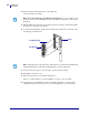
5. Fold the cable and the ferrite bead back over the mounting bracket, and connect the ribbon
cable connector into the keyed Interface Data Cable Connector (J4) on the main logic
board. Secure the
PSII interface board in place with the cover plate screws that you
removed early in this step sequence.
6. Confirm that all small cable connectors are tight.
7. Reinstall the PA X series PCB access panel or the left side-panel of the XiII and XiIII series
printers that you removed earlier in this step sequence.
8. This kit includes a label printed with the Ethernet MAC hardware address for the PSII.
Remove the backing from the label and affix it to the back of the printer.
9. Reconnect the AC power cord and turn the printer on.
10. Consult your System Administrator before configuring the PSII for your network! To
establish the network connection, refer to the section applicable to your network type.
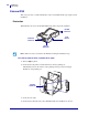
Z4Mplus/Z6Mplus
This illustration shows you the internal PSII that can be installed into Z4Mplus and Z6Mplus
printers. The components you need to be familiar with are:
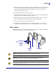
Caution • A qualified service technician must perform this installation.
Caution • Observe proper electrostatic safety precautions when handling any
static-sensitive components such as circuit boards and printheads.
Caution • Turn off (O) the printer and disconnect it from the power source before
performing the following procedure.
Test Button
Ethernet Connector
Status
Indicator
(Green)
Parallel Port
Socket
Cable
Status
Indicator
(Red)