Operations Load Media in Rewind Mode 13. Extend approximately 36 in. (920 mm) of media out of the printer. Remove and discard the labels from this exposed media. 14. Remove the hook from the rewind spindle. 15. If you are using a core, slide it onto the rewind spindle until it is flush against the guide plate. Note • A core is not required. 16. Wind the media liner counterclockwise around the rewind spindle. 17. Reinstall the hook.
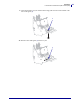
62 Operations Load Media in Rewind Mode 2 1 18. Rotate the spindle counterclockwise several turns to wind the media liner over the hook and remove any slack. 19. Align the media with the inner media guide (1). Slide in the outer media guide (2) until it just touches the edge of the media.
Operations Load Media in Rewind Mode 20. Tighten the thumb screw (not visible from this angle) that is located on the bottom of the outer media guide (1). 1 21. Push down the printhead assembly (1), and then rotate the printhead-open lever (2) clockwise until it locks into place. 2 1 The labels wind on the rewind spindle or core.
64 Operations Load Media in Rewind Mode Remove Media Liner from the Rewind or Peel Spindle Rewind mode and Peel-Off mode each use spindles to wind used media liner. Remove the media liner from the spindle each time that you change labels. Important • It is not necessary to turn off the power to remove media liner from the spindle. If power is turned off, all label formats and images, as well as any temporarily saved parameter settings stored in the printer’s internal memory, are lost.
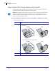
Operations Load Media in Rewind Mode 2. Pull out the spindle hook. Rewind Peel 3. Slide the media liner off of the spindle and discard.
6 Operations Load Media in Rewind Mode (with Cutter Option) Load Media in Rewind Mode (with Cutter Option) Some printers with the Cutter option can use Rewind mode to print and save a roll of labels (Figure 10). This section shows how to load media for Rewind mode in printers that have a Cutter option. Note • Rewind mode cannot be used with the Cutter option on 110Xi4 printers.
Operations Load Media in Rewind Mode (with Cutter Option) Caution • While performing any tasks near an open printhead, remove all rings, watches, hanging necklaces, identification badges, or other metallic objects that could touch the printhead. You are not required to turn off the printer power when working near an open printhead, but Zebra recommends it as a precaution.
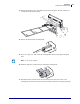
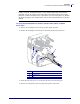
68 Operations Load Media in Rewind Mode (with Cutter Option) 5. Push the top edges of the rewind plate until the rewind plate snaps into place in the slots on the cutter. 6. Set the printer to Rewind mode. See Select Print Mode on page 101 for instructions. 7. Insert media into the printer. See Prepare the Media for Loading on page 37 for instructions. 8. Open the printhead assembly by rotating the printhead-open lever (1) counter-clockwise.
Operations Load Media in Rewind Mode (with Cutter Option) 9. Loosen the thumb screw (not visible from this angle) that is located on the bottom of the outer media guide (1). 1 10. Slide the outer media guide (1) all the way out.
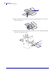
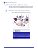
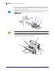
70 Operations Load Media in Rewind Mode (with Cutter Option) 11. If your printer includes a media dancer assembly (1), thread the media under the media dancer assembly roller. For all printers, thread the media under the media guide roller (2) and then the upper media sensor (3). Important • Make sure that you thread the media under these components. If you thread the media over the them, the media obstructs the ribbon sensor and causes a false RIBBON OUT error. 3 2 1 12.
Operations Load Media in Rewind Mode (with Cutter Option) 13. Extend approximately 36 in. (920 mm) of media out of the printer. Remove and discard the labels from this exposed media. 14. Remove the hook from the rewind spindle. 15. If you are using a core, slide it onto the rewind spindle until it is flush against the guide plate. Note • A core is not required. 16. Wind the media liner counterclockwise around the rewind spindle. 17. Reinstall the hook.
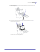
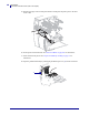
72 Operations Load Media in Rewind Mode (with Cutter Option) 2 1 18. Rotate the spindle counterclockwise several turns to wind the media liner over the hook and remove any slack. 19. Align the media with the inner media guide (1). Slide in the outer media guide (2) until it just touches the edge of the media.
Operations Load Media in Rewind Mode (with Cutter Option) 20. Tighten the thumb screw (not visible from this angle) that is located on the bottom of the outer media guide (1). 1 21. Push down the printhead assembly (1), and then rotate the printhead-open lever (2) clockwise until it locks into place. 2 1 The labels wind on the rewind spindle or core. 22. For instructions for removing the labels from the rewind spindle, see Remove Media Liner from the Rewind or Peel Spindle on page 64.
74 Operations Load Ribbon Load Ribbon Use the instructions in this section to load ribbon for use with thermal transfer labels. For direct thermal labels, do not load ribbon in the printer. The ribbon path is slightly different for printers with ribbon dancers (Figure 11). Important • Use ribbon that is wider than the media to protect the printhead from wear. Ribbon must be coated on the outside.
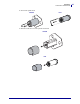
Operations Load Ribbon 2. Align the segments of the ribbon supply spindle. 3. Orient the ribbon with the loose end unrolling clockwise. 4. Place the roll of ribbon on the ribbon supply spindle. Push the roll back as far as it will go. 5. A ribbon leader makes ribbon loading and unloading easier. Does your roll of ribbon have paper or something else attached to the end to serve as a ribbon leader? If… Then… Yes Continue with the next step. No a.
76 Operations Load Ribbon 6. Open the printhead assembly by rotating the printhead-open lever counter-clockwise. 7. Does your printer contain a ribbon dancer assembly? (See Figure 11 on page 74 for the ribbon dancer location.) If... Then... No Thread the ribbon over the media dancer assembly (1) and under the ribbon guide roller (2).
Operations Load Ribbon If... Then... Yes a. Thread the ribbon through the ribbon dancer. The ribbon must go under the upper roller (1) and then over the lower roller (2). b. Thread the ribbon under the ribbon guide roller (3). 3 2 1 8. Push the ribbon leader forward until it passes under the printhead assembly (1), over the snap plate (2), and then over the platen roller (3).
78 Operations Load Ribbon 9. Bring the ribbon leader over the upper ribbon roller (1) and then toward the ribbon take-up spindle (2). 1 2 10. Wind the ribbon leader and attached ribbon counterclockwise around the ribbon take-up spindle. 11. Rotate the spindle counterclockwise several turns to wind the ribbon and remove any slack.
Operations Load Ribbon 12. Push down the printhead assembly (1), and then rotate the printhead-open lever (2) clockwise until it locks into place. 2 1 Remove Used Ribbon Remove used ribbon from the ribbon take-up spindle each time you change the roll of ribbon. To remove used ribbon, complete these steps: 1. Has the ribbon run out? 2/23/09 If the ribbon... Then Ran out Continue with the next step. Did not run out Cut or break the ribbon before the ribbon take-up spindle.
80 Operations Load Ribbon 2. While holding the ribbon take-up spindle, turn the ribbon release knob clockwise until it stops. The ribbon release bars pivot down, easing the spindle’s grip on the used ribbon. 3. Slide the used ribbon off of the ribbon take-up spindle and discard.
Operations Calibrate the Printer Calibrate the Printer Calibrate the printer when it is first put into service. Calibration allows the printer to establish the proper settings for the specific media and ribbon used in your application. You may calibrate the printer at other times as needed. Table 8 shows the different methods for calibration.
82 Operations Calibrate the Printer Table 8 • Types of Calibration (Continued) Type of Calibration Description When/How It Occurs Sensor Profile Calibration The printer auto-calibrates and prints a media sensor profile. Select the SENSOR PROFILE option on the control panel. See Print Sensor Profile on page 108 for instructions. Media and Ribbon Sensor Sensitivity Calibration One of the most common adjustments to printer settings.
Operations Adjust Media Sensors Adjust Media Sensors The transmissive sensor consists of two sections: a light source (the lower media sensor) and a light sensor (the upper media sensor). The media passes between the two. Adjust these sensors only when the printer cannot detect the top of the label. The control panel LCD displays ERROR CONDITION PAPER OUT, even though there are labels loaded in the printer.
84 Operations Adjust Media Sensors 3. Using a thin, flat-blade screwdriver, loosen the upper media sensor adjustment screw. Z X Y 4. Slide the upper media sensor along the slot to the desired position (for non-continuous media with a notch or hole in the media, the sensor must be directly above the notch or hole). Z X Y 5. Tighten the adjustment screw to secure the upper media sensor. Z X Y 6. Adjust the lower media sensor to match the new position of the upper media sensor.
Operations Adjust Media Sensors Upper Media Sensor—Outside Half of Media To adjust the upper media sensor for the outside half of the media, complete these steps (all models except the 220Xi4): 1. Remove the ribbon (if ribbon is used). 2. Locate the upper media sensor adjustment screw (1). The upper media sensor eye is directly below the adjustment screw head. 1 Z X Y 3. Using a thin, flat-blade screwdriver, loosen and then remove the upper media sensor adjustment screw. Z X Y 4.
86 Operations Adjust Media Sensors 6. Slide the upper media sensor along the slot to the desired position (for non-continuous media with a notch or hole in the media, the sensor must be directly above the notch or hole). Z X Y 7. Tighten the adjustment screw. Z X Y 8. Make sure that the wires are routed back into the groove of the media sensor bracket. 9. Adjust the lower media sensor to match the new position of the upper media sensor. See Lower Media Sensor on page 87.
Operations Adjust Media Sensors Lower Media Sensor After you adjust the upper media sensor, adjust the lower media sensor to match its new position. To adjust the lower media sensor, complete these steps: 1. Locate the lower media sensor assembly under the rear roller. The sensor is a spring clip holding a circuit board. 2. Slide the lower sensor until it is under the upper media sensor. Use the light that shines from the sensor to help align it with the upper sensor.
88 Operations Adjust Printhead Pressure and Toggle Position Adjust Printhead Pressure and Toggle Position Print quality depends on the labels and ribbon used as well as the toggle pressure and position. Make sure that your labels and ribbon are acceptable for your application. If they are, check the toggle position and then the printhead pressure. Toggle Position Adjustment You may need to adjust the toggles if printing is too light on one side or if thick labels are used.
Operations Adjust Printhead Pressure and Toggle Position Printhead Pressure Adjustment If positioning the toggles properly does not solve a print quality problem, try adjusting the printhead pressure. Maximize printhead life by using the lowest pressure that produces the desired print quality. Caution • Observe proper electrostatic safety precautions when handling any static-sensitive components such as circuit boards and printheads. To adjust printhead pressure, complete these steps: 1.
90 Operations Adjust Printhead Pressure and Toggle Position 4. Some media types require higher pressure to print well. For these media types, increase or decrease pressure using the lower knurled nuts (1) until the left and right edges of the printed area are equally dark. 1 5. Increase the darkness level using the control panel controls until the printing is clear. 6. Tighten the upper knurled nuts.
Operations Adjust Printhead Pressure and Toggle Position Notes • ___________________________________________________________________ __________________________________________________________________________ __________________________________________________________________________ __________________________________________________________________________ __________________________________________________________________________ __________________________________________________________________________ __
92 Operations Adjust Printhead Pressure and Toggle Position P1009874-001 Xi4 User Guide 2/23/09
4 Configuration This section describes the control panel parameters that are used to configure the printer for operation. Contents Setup Mode . . . . . . . . . . . . . . . . . . . . . . . . . . . . . . . . . . . . . . . . . . . . . . . . . . . . . . . . . . . 94 Enter and Use Setup Mode . . . . . . . . . . . . . . . . . . . . . . . . . . . . . . . . . . . . . . . . . . . . . 94 Exit Setup Mode. . . . . . . . . . . . . . . . . . . . . . . . . . . . . . . . . . . . . . . . . . . . . . . . . . . . . .
94 Configuration Setup Mode Setup Mode After you have installed the media and ribbon and the Power-On Self Test (POST) is complete, the control panel displays PRINTER READY. You may now set printer parameters for your application using the control panel display and the buttons directly below it. If it becomes necessary to restore the initial printer defaults, see FEED and PAUSE Self Test on page 158.
Configuration Setup Mode Exit Setup Mode When you exit setup mode, you have several options for saving, changing, or not changing parameters. To leave Setup mode, complete these steps: 1. Press SETUP/EXIT. The LCD displays SAVE CHANGES. 2. Press PLUS (+) or MINUS (-) to display the save options: LCD Description PERMANENT Stores values in the printer even when power is turned off. TEMPORARY Saves the changes until power is turned off.
96 Configuration Change Password-Protected Parameters Change Password-Protected Parameters Certain parameters, including the communication parameters, are password-protected by factory default. Caution • Do not change password-protected parameters unless you have a complete understanding of the parameters’ functions. If the parameters are set incorrectly, the printer may function unpredictably. The first time that you attempt to change a password-protected parameter, the printer displays ENTER PASSWORD.
Configuration Print a Configuration Label Print a Configuration Label A configuration label lists the printer settings that are stored in configuration memory. After you load the media and ribbon (if necessary), print a configuration label as a record of your printer’s current settings. Keep the label to use when troubleshooting printing problems. To print a configuration label, complete these steps: 1. On the control panel, press SETUP/EXIT. 2.
98 Configuration Print a Network Configuration Label Print a Network Configuration Label If you are using a print server, you can print a network configuration label after the printer is connected to the network. To print a network configuration label, complete these steps: 1. On the control panel, press SETUP/EXIT. 2. Press NEXT/SAVE or PREVIOUS to scroll through the parameters until you reach LIST NETWORK. 3. Press PLUS (+) to confirm printing. A network configuration label prints (Figure 13).
Configuration Standard Control Panel Parameters Standard Control Panel Parameters Table 9 shows parameters in the order in which they are displayed when you press NEXT/SAVE after entering Setup mode. For parameters that do not appear in this table, see Additional Control Panel Parameters on page 121. Note • Your label preparation software or the printer driver may override adjustments made through the control panel. Refer to the software or driver documentation for more information.
100 Configuration Standard Control Panel Parameters Table 9 • Printer Parameters (Continued, page 2 of 22) Language/Parameter Action/Explanation Adjust Print Speed Adjusts the speed for printing a label (given in inches per second). Slower print speeds typically yield better print quality. Print speed changes take effect upon exiting Setup mode. Default Value: 2 IPS Range: • 200 dpi: 2 to 10 IPS • 300 dpi: 2 to 8 IPS • 600 dpi: 1 to 4 IPS To change the value shown: Press PLUS (+) to increase the value.