Color profile: Disabled Composite Default screen User's Guide For the Zebra Z4000™ and Z6000™ Printers Customer order # 77460L 1 H:...uspiran2.vp Thu Jun 18 15:49:04 1998 Manufacturer part # 77460LB Rev.
Color profile: Disabled Composite Default screen Proprietary Statement This manual contains proprietary information of Zebra Technologies Corporation. It is intended solely for the information and use of parties operating and maintaining the equipment described herein. Such proprietary information may not be used, reproduced, or disclosed to any other parties for any other purpose without the expressed written permission of Zebra Technologies Corporation.
Color profile: Disabled Composite Default screen Z Series™ User’s Guide 3 H:...uspiran2.
Color profile: Disabled Composite Default screen ii Z Series™ User’s Guide 4 H:...uspiran2.
Color profile: Disabled Composite Default screen Contents Welcome Getting Started 1 Communications 2 Printer Power 2 Printer Configuration Z Series™ Configuration Media & Ribbon Loading Loading Media 5 Loading Ribbon 7 Removing Ribbon 8 Media Sensor Positioning Media Sensor Operation 9 Media Sensor Position 9 Printer Operational Check Printer Operation 10 Operator Interface 13 Front Panel Keys 13 Front Panel LEDs 14 Additional Front Panel Controls 14 Z Series™ User’s Guide 5 H:
Color profile: Disabled Composite Default screen Media Calibration Auto-Calibration 17 Calibration Control 17 Care & Adjustments Cleaning 19 Lubrication 24 Printhead Pressure Adjustment 24 Power Rewind/Power Peel Media Alignment 25 Printer Options LCD Display (Deluxe Front Panel) 27 Power Rewind/Power Peel Option 28 Value Peel Option 30 Cutter Option 31 Electronics Options 33 Communication Options 33 Troubleshooting iv Power On Self-Test 35 Troubleshooting Tables 35 Printer S
Color profile: Disabled Composite Default screen Printer Specifications General Specifications 47 Printing Specifications 48 Ribbon Specifications 48 Media Specifications 49 Zebra Programming Language (ZPL II®) 50 Bar Codes 50 Standard Printer Fonts 51 Optional Printer Fonts 53 Appendix A Printer Configuration (Standard Front Panel) 55 Printer Configuration (Deluxe Front Panel) 59 Appendix B Communication Interfaces 69 Serial Data Communications 69 Parallel Data Communications 72
Color profile: Disabled Composite Default screen vi Z Series™ User’s Guide 8 H:...uspiran2.
Color profile: Disabled Composite Default screen Welcome Congratulations! You have just purchased a high-quality thermal demand printer manufactured by the industry leader in quality, service, and value. For over 25 years, Zebra Technologies Corporation has provided customers with the highest caliber of products and support. This user’s guide provides all the information you will need to operate the printer on a daily basis.
Color profile: Disabled Composite Default screen For shipping information, refer to Appendix C. Communications Refer to Figure 1. The Z Series™ printer comes standard with both an Electronics Industries Association (EIA) RS-232 serial data interface(a) and a bi-directional parallel interface(b) compliant with the IEEE1284 standard. The serial interface is also configured for both RS-422/ RS-485 single drop and RS-485 multi-drop communication modes.
Color profile: Disabled Composite Default screen Printer Configuration Z Series™ Configuration The Z Series™ printer will have one of two different styled front panels. The deluxe front panel contains an LCD (Liquid Crystal Display), but the standard front panel does not. With the deluxe front panel, the LCD displays the parameters during the configuration process.
Color profile: Disabled Composite Default screen Operating Modes When shipped from the factory, the printer is preset to the most commonly used modes of operation: Tear-Off Mode, Thermal Transfer Printing, Die-Cut Media, Serial Port RS-232 Communications.
Color profile: Disabled Composite Default screen Media & Ribbon Loading Loading Media To load media, refer to Figure 2. 1. Raise the media cover. 2. Press the Printhead Open Lever(e). [The Printhead Assembly(f) automatically springs up.] 3. Fold down the Media Supply Guide(g) and slide it out as far from the printer frame as possible. 4. Slide the Media Guide(h) out as far from the printer frame as possible. 5.
Color profile: Disabled Composite Default screen Roll Media Loading To load roll media, refer to Figure 3. 1. Place the roll of media on the Media Supply Hanger(i) and push it on all the way. 2. Fold the Media Supply Guide(g) up and slide it against the outer edge of the media roll. 3. Feed the media under the Media Spindle(j), under the Ribbon Sensor(k), and out the front of the printer. 4. Slide the Media Guide(h) in until it is against the outer edge of the media. 5.
Color profile: Disabled Composite Default screen g i k j h Figure 4. Fanfold Media Loading Loading Ribbon NOTE: The Ribbon Supply Spindle in your printer may be a "Dual-Tension" variety. Most applications require the spindle to be in the "Normal" position. The "Low-Tension" position is recommended only when wide ribbons are used and normal tension hampers the ribbon movement.
Color profile: Disabled Composite Default screen Loading the Ribbon CAUTION: Always use ribbon that is wider than the media. The smooth backing of the ribbon protects the printhead from wear. (For Direct Thermal printing, do not load ribbon in the printer.) To load ribbon, refer to Figures 5a and 5b. 1. 2. 3. 4. Place the roll on the Ribbon Supply Spindle(l) and push it on all the way.
Color profile: Disabled Composite Default screen Media Sensor Positioning Media Sensor Operation When the printer is turned ON, a Power ON Self Test is performed which checks the status of the electronic system and controls within the printer. Additional operating parameters are determined by the type of media being used and the position of the Media Sensor located behind the Platen and under the media.
Color profile: Disabled Composite Default screen 5. 6. sensor anywhere under the media so that an “Out-of-Media” condition will still be sensed. Insure the media and ribbon are properly positioned within the print mechanism. then close the Printhead Assembly. Close the printer’s media cover, then turn the printer power OFF. o p Figure 6. Sensor Positioning Printer Operational Check 1.
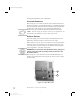
Color profile: Disabled Composite Default screen next. To maintain proper print quality, refer to the Care & Adjustments section later in this guide. Figure 7 illustrates a properly loaded Z Series™ printer. For loading media and ribbon in printers with the Power Rewind/Power Peel, Value Peel or Cutter options, see the Options section later in this guide. Figure 7. Printer Ready for Operation Z Series™ User’s Guide 19 H:...uspiran2.
Color profile: Disabled Composite Default screen 12 Z Series™ User’s Guide 20 H:...uspiran2.
Color profile: Disabled Composite Default screen Printer Operation Operator Interface The Z Series™ family of printers features either a standard or deluxe front panel. The deluxe front panel features a Liquid Crystal Display (LCD) that provides both printer status information and configuration option menus. This section of the user’s guide presents information which is common to both printer front panels. Refer to Figures 8 and 9 to locate the keys and LEDs discussed in this section.
Color profile: Disabled Composite Default screen Front Panel LEDs LEDs on the front panel are a quick indication of the printer's status. The LEDs listed below are common to all Z Series™ printers . POWER LED The POWER LED is always ON when the printer is turned ON. DATA LED The DATA LED is normally OFF.
Color profile: Disabled Composite Default screen Figure 8. Standard Front Panel Figure 9. Deluxe Front Panel Z Series™ User’s Guide 23 H:...uspiran2.
Color profile: Disabled Composite Default screen 16 Z Series™ User’s Guide 24 H:...uspiran2.
Color profile: Disabled Composite Default screen Media Calibration Auto-Calibration The auto-calibration of the Z Series™ printer occurs at power ON and each time the printer recovers from error conditions such as media errors, ribbon errors, and printhead open errors. In the process of clearing an error, open and close the printhead then take the printer out of PAUSE. The printer will begin the auto-calibration process if all errors have been cleared.
Color profile: Disabled Composite Default screen 18 Z Series™ User’s Guide 26 H:...uspiran2.
Color profile: Disabled Composite Default screen Care & Adjustments Cleaning CAUTION: Use only the cleaning agents indicated. Zebra Technologies Corporation will not be responsible for damage caused by any other cleaning materials used on the Z Series™ printer. Table 1 provides a recommended cleaning schedule. Cleaning Swabs saturated with 70% Isopropyl Alcohol are available from your Zebra distributor as a Preventive Maintenance Kit (part # 01429). AREA METHOD See Figure 10 for parts callouts.
Color profile: Disabled Composite Default screen Cleaning the Interior Remove any accumulated dirt and lint from the interior of the printer using a soft bristle brush and/or vacuum cleaner. Cleaning the Printhead and Platen Roller Inconsistent print quality, such as voids in the bar code or graphics, may indicate a dirty printhead. For best results, perform the following cleaning procedure after every roll of ribbon. NOTE: The printer can remain ON while you are cleaning the printhead.
Color profile: Disabled Composite Default screen q o r k e Figure 10. Printhead and Platen Roller Cleaning Z Series™ User’s Guide 29 H:...uspiran2.
Color profile: Disabled Composite Default screen Cleaning the Cutter Module (For printers equipped with the Cutter option.) The Cutter Module requires periodic cleaning to remove paper dust and gummed label residue. If labels are not being cut properly, or if the cutter jams with labels, this is an indication that the cutter probably needs cleaning. The cleaning frequency depends on your application and the type of media you use.
Color profile: Disabled Composite Default screen Figure 11. Cutter Cleaning NOTE: Disassembly of the Cutter module should only be performed by a Service Technician. Z Series™ User’s Guide 31 H:...uspiran2.
Color profile: Disabled Composite Default screen Cleaning the Peel Blade (For printers equipped with the Value Peel or Power Peel option.) 1. Open the Media Door and press the Printhead Open Lever to raise the Printhead Assembly. 2. Refer to Figure 12. Open the Peel Mechanism by gently lifting up on the Media Plate and pivoting it toward you. 3. Refer to Figure 12. The primary area requiring cleaning is the backside of the Separator Bar. 4.
Color profile: Disabled Composite Default screen Lubrication CAUTION! No lubricating agents of any kind should be used on this printer! Some commercially available lubricants, if used, will damage the finish and the mechanical parts inside the printer. Printhead Pressure Adjustment Printhead pressure is adjustable to insure maximum print quality.
Color profile: Disabled Composite Default screen Power Rewind/Power Peel Media Alignment (For printers equipped with the Power Rewind/Power Peel option.) An adjustment to the Media Alignment Spindle allows the user to insure that the media or backing material is properly winding onto the Take-up Spindle. Refer to Figure 14. Turn the adjustment dial(v) clockwise to align the media/backing material more to the left.
Color profile: Disabled Composite Default screen Printer Options LCD Display (Deluxe Front Panel) The Z Series™ printers include the option of replacing the standard front panel with a deluxe front panel containing a Liquid Crystal Display (LCD). The LCD shows several types of information. n When the printer completes its Power ON Self Test, the LCD displays an “idle” message. PRINTER READY 1024K Vxx.x.x n While a format is printing, a label counter is displayed.
Color profile: Disabled Composite Default screen Power Rewind/Power Peel Option The Z Series™ printer supports a rewind option, with the capability of rewinding an entire roll of printed labels (Rewind mode) or backing material only (Peel mode). This option is available as both a factory installed feature and a field-installable kit. Label Movement in Rewind Mode In the Rewind mode, labels are printed and fed forward in a continuous sequence.
Color profile: Disabled Composite Default screen Media Loading Refer to Figure 15 (Power Rewind) or Figure 16 (Power Peel) while loading media. 1. Place the roll of media on the Media Supply Hanger(i) and push it on all the way. 2. Fold the Media Supply Guide(g) up and slide it against the outer edge of the media roll. 3. Press the Printhead Open Lever(e) and raise the Printhead Assembly. 4. Feed the media under the Media Spindle(j), under the Ribbon Sensor(k), and out the front of the printer. 5.
Color profile: Disabled Composite Default screen 8. Loosen the thumbscrew and slide the Rewind Media Guide(x) out to the end of the spindle and rotate it to its horizontal position. 9. Place an empty media core on the Rewind Spindle(y), wrap the media around the core, and turn the spindle counterclockwise to wind up the excess material. 10. Rotate the Rewind Media Guide to its vertical position, slide it in against the media, and tighten the thumbscrew that locks it into position. 11.
Color profile: Disabled Composite Default screen Media Loading Refer to Figure 17 while loading media. 1. Place the roll of media on the Media Supply Hanger(i) and push it on all the way. 2. Fold the Media Supply Guide(g) up and slide it against the outer edge of the media roll. 3. Press the Printhead Open Lever(e) and raise the Printhead Assembly. 4. Feed the media under the Media Spindle(j), under the Ribbon Sensor(k), and out the front of the printer. 5.
Color profile: Disabled Composite Default screen Cutter Option The Z Series™ printer also features a cutter option. This option is available as both a factory installed feature and a field installable kit. A label catch tray is included which holds up to 10 labels up to 6” in length. Label Movement in Cutter Mode When the label is completely printed, the printer feeds the media into the cutter mechanism. The cutter blade is activated and the printer waits for the cutter mechanism to complete its cycle.
Color profile: Disabled Composite Default screen 4. 5. 6. Feed the media under the Media Spindle(j), under the Ribbon Sensor(k), through the Cutter Module, and out the front of the printer. Slide the Media Guide(h) in against the outer edge of the media. Go to the “Loading Ribbon” procedure earlier in this guide; then continue through the “Configuration” and “Media Sensor Positioning” processes. Z Series™ User’s Guide 41 H:...uspiran2.
Color profile: Disabled Composite Default screen Electronics Options PCMCIA Option An optional PCMCIA Port is available for the Z Series™ printer. This option is available as both a factory installed feature and a field installable kit. Access to the PCMCIA port is from the rear of the printer. Optional PCMCIA Memory Cards will provide non-volatile storage for label formats, downloadable fonts, graphics files, etc. The content of the PCMCIA Memory Card is not lost when power is turned OFF.
Color profile: Disabled Composite Default screen Once the option is installed in the printer, information to be stored in Flash Memory is downloaded to the printer from the host computer. A specific ZPLcommand is then sent to the printer which causes the information to be stored in the Flash Memory. The content of the Flash Memory is not lost when power is turned OFF.
Color profile: Disabled Composite Default screen 36 Z Series™ User’s Guide 44 H:...uspiran2.
Color profile: Disabled Composite Default screen Troubleshooting Power On Self-Test A Power On Self Test (POST) is performed each time the printer is turned ON. During this test, the front panel LEDs will turn ON and OFF to ensure proper operation. At the end of this self test, only the POWER LED will remain lit. Once the Power ON Self Test is complete, the media is advanced to the proper rest position as determined by the programmed media feed setting.
Color profile: Disabled Composite Default screen SYMPTOM DIAGNOSIS ACTION Printer stops, PAUSE Printhead is not fully Close printhead LED ON and ERROR closed. completely. Malfunctioning Call a Service Printhead Open Sensor. Technician. Printer stops, PAUSE Printer in Peel mode Change printer LED BLINKING. and no Peel option operating mode to installed. fit application. Printer stops. PAUSE Printhead element is Printer resumes printing LED ON and ERROR overheated.
Color profile: Disabled Composite Default screen SYMPTOM DIAGNOSIS Wrinkled ribbon. Ribbon fed through ACTION Reinstall ribbon. printer incorrectly. Incorrect Darkness Set to the lowest value setting. needed for good print quality. Incorrect Printhead Readjust Printhead pressure. pressure. Media not feeding Readjust Media Guides. properly; it is walking from side to side. Continuing problems. Call a Service Technician.
Color profile: Disabled Composite Default screen SYMPTOM DIAGNOSIS ACTION In Peel-Off Mode, Glue material from Perform maintenance skewed or stuck labels. back of labels causing and clean the printer. media movement problems. Labels are not being cut. Media and backing not Check media guide aligned in printer. positions. Cutter Mode not Reconfigure the printer. selected. The Cutter is not cutting Cutter is dirty. Clean Cutter Blades. Cutter Blades are dull. Replace Cutter Module.
Color profile: Disabled Composite Default screen Make sure that your print width is set correctly for the media you are using before you run any self-tests, otherwise the test may print out on the platen. If your media is not wide enough or long enough to display a complete test label, unexpected and/or undesired results may occur. When performing these self-tests while in the Peel Mode, you must remove the labels as they become available.
Color profile: Disabled Composite Default screen PAUSE Key Self-test Press and hold the PAUSE key while turning the printer power ON. Release the key anytime after the first front panel LED turns OFF. The PAUSE key self-test prints a series of labels which can be used when making print quality adjustments.
Color profile: Disabled Composite Default screen FEED Key Self-test Press and hold the FEED key while turning the printer power ON. Release the key anytime after the first front panel LED turns OFF. The quantity of labels printed during this print quality test depends on the dot density of the printhead. n 300 dpi printers: 7 labels are printed at the 2 ips and 6 ips print speeds. n 200 dpi printers: 7 labels are printed at the 2 ips, 6 ips and 10 ips print speeds.
Color profile: Disabled Composite Default screen PAUSE and CANCEL Key Self-test Press and hold both the PAUSE key and CANCEL key while turning the printer power ON. Release both keys anytime after the first front panel LED turns OFF. The PAUSE and CANCEL key self-test prints a sequentially numbered series of 500 labels. When making print quality adjustments, these labels should be observed o insure the highest print quality has been set. Figure 22 provides an example of the FEED key self-test label.
Color profile: Disabled Composite Default screen Communications Diagnostic Self-test The Communications Diagnostic Mode is a troubleshooting tool for checking the interconnection between the printer and the host computer.When “Diagnostics” is selected, all data sent to the printer will be printed as straight ASCII hex characters. The printer prints all received characters including control codes like CR (Carriage Return).
Color profile: Disabled Composite Default screen Media and Ribbon Sensor Profile The Media and Ribbon Sensor Profile may be used to troubleshoot registration problems that may be caused when the Media Sensor experiences difficulty in determining web location between labels. To print a Media and Ribbon Sensor Profile, you must press and hold the PAUSE key, FEED key, and CANCEL key while turning the printer power ON. Release all three keys anytime after the first front panel LED turns OFF.
Color profile: Disabled Composite Default screen Initializing the Flash Memory and PCMCIA Card As of Firmware release V22.8.4, a new procedure is used to initialize the optional on-board Flash Menory device and the optional PCMCIA Card. Prior to uploading new contents into the Flash Memory and/or the PCMCIA Card, it is first necessary to initialize these devices.
Color profile: Disabled Composite Default screen Print Error Conditions There are several error conditions that effect printing. Some actually stop the printing process completely, while others are only reported to the operator or host system. A printhead open error condition stops any media movement, while the printhead under temperature error has no effect on media movement. Some error conditions must be corrected before the printer will feed or print labels again.
Color profile: Disabled Composite Default screen Printer Specifications NOTE: Printer specifications are subject to change without notice. Your printer may not have all of the options described in these specifications. If you have questions as to the ability of the Z Series™ printer to meet the needs of your application, contact either your Zebra Distributor or Zebra Technologies Corporation.
Color profile: Disabled Composite Default screen Printing Specifications PRINTING SPECIFICATIONS Z 4000 PRINTER Z 6000 PRINTER 203 dpi (8 dots/mm) or 300 dpi (11.8 dots/mm) 203 dpi 0.00492 (0.125 mm) square 300 dpi 0.0033x0.0039(0.84mmx0.99mm) Maximum print width 4.1 (104 mm) 6.6 (168 mm) Print length Minimum 1 dot row Maximum Std memory continuous 8 dot/mm 37 (940 mm) 23 (584 mm) 12 dot/mm 16 (406 mm) 10 (254 mm) media (* 39 Max Opt memory for nondot/mm *136 (3.5 m) *84 (2.
Color profile: Disabled Composite Default screen Media Specifications MEDIA SPECIFICATION Total media width Label length Maximum Minimum Maximum Minimum Tear-Off Mode Rewind Mode Peel-Off Mode Cutter Mode Total thickness Maximum ( (includes liner) ) Minimum Core size Maximum roll diameter Inter-label gap Maximum Minimum [ ] Ticket/tag notch size (Width x Length) If above 0.01", printhead pressure may need adjustment 0.118 (3 mm) preferred Z 4000 PRINTER Z 6000 PRINTER 4.5 (115 mm) 7.
Color profile: Disabled Composite Default screen Zebra Programming Language (ZPL II®) n Downloadable graphics (with n Programmable quantity with print data compression) pause n Bit image data transfer and print- n Communicates in printable ing, mixed text/graphics n Format inversion ASCII characters n Controlled via mainframe, mini, PC, Portable Data Terminal n Mirror image printing n Four-position field rotation (0°, 90°, 180°, 270°) n In-Spec OCR-A and OCR-B n UPC/EAN [nominal 100% magnification (
Color profile: Disabled Composite Default screen Standard Printer Fonts For more information on fonts, refer to the ZPL II Programming Guide. 203 DOTS/INCH (8 DOTS/MM) PRINTHEAD Dot Matrix (h x w) Minimum Character Size (h x w) Max Char /In (Defaults) A 9x5 U-L-D 0.044 x 0.030 33.3 B 11 x 7 U 0.054 x 0.044 22.7 C, D 18 x 10 U-L-D 0.089 x 0.059 16.9 E 28 x 15 OCR-B 0.138 x 0.098 10.2 F 26 x 13 U-L-D 0.128 x 0.079 12.7 G 60 x 40 U-L-D 0.295 x 0.236 4.2 H 21 x 13 OCR-A 0.103 x 0.093 10.
Color profile: Disabled Composite Default screen Standard Printer Font Examples Default Printer Fonts - 300 dots/inch (12 dots/mm) Default Printer Fonts - 203 dots/inch (8 dots/mm) 54 Z Series™ User’s Guide 62 H:...uspiran2.
Color profile: Disabled Composite Default screen Optional Printer Fonts There are many optional character fonts that can be purchased for your Z Series™ printer, in addition to those which are standard in the unit. From time to time, additions may be made to the list of available fonts. Contact your sales representative for further information. Once installed, the optional fonts can be used in addition to the standard fonts available in the printer.
Color profile: Disabled Composite Default screen 56 Z Series™ User’s Guide 64 H:...uspiran2.
Color profile: Disabled Composite Default screen Appendix A Printer Configuration (Standard Front Panel) NOTE: To configure a Z Series™ printer having the optional deluxe front panel, refer to the information found later in this section. Serial Communications Parameters Refer to Figure 25. When using serial communication, the Bank One (left) switches inside the front panel door must match the communication parameters of the printer with those of your host computer.
Color profile: Disabled Composite Default screen Refer to Table 8 if the settings need to be changed to match those of your host computer. If you do not know the settings of your host computer, refer to the instruction manual provided with the computer. The serial port supports an Error Detection Protocol which sends and receives data in packets. This “Zebra” protocol must be compatible with your host computer and your application software. Received packets are checked for accuracy.
Color profile: Disabled Composite Default screen Operating Modes Use the Bank Two (right) switches to select printer operating modes. When shipped from the factory, all switches are in the ON position. This presets the printer to match the most commonly used modes of operation - Tear-Off Mode, Non-continuous Media, Thermal Transfer Operation, and RS-232 Serial Communications.
Color profile: Disabled Composite Default screen Standard Front Panel Control Keys If you need to adjust the print darkness, label position or the image position on the label, use the following control keys located inside the front panel door to configure these parameters. Print Darkness Key Press this key (LED turns ON) to change the print darkness setting by pressing the PLUS (+) or MINUS (-) keys. Each press of the + or - key changes the setting by one step.
Color profile: Disabled Composite Default screen Printer Configuration (Deluxe Front Panel) NOTE: To configure a Z Series™ printer having the standard front panel, refer to the information found earlier in this section. Deluxe Front Panel Control Keys Refer to Figure 26. Opening the door on the front panel provides access to the control keys used for configuring the printer’s operating features. The Liquid Crystal Display (LCD) shows the menus as you proceed through the configuration process.
Color profile: Disabled Composite Default screen NEXT MENU Key Press this key to increment through the major menu headings, showing the top level of each configuration section. When the end of the menu listing is reached, the list repeats automatically. NEXT ITEM Key Once the appropriate major menu is visible on the LCD display, the NEXT ITEM key can be used to sequence through the configuration prompts for that menu. When the end of the item listing is reached, the list repeats automatically.
Color profile: Disabled Composite Default screen PARAMETER LANGUAGE DARKNESS TEAR OFF PRINT MODE LABEL TOP LCD ADJUST GENERAL SETUP MENU SELECTIONS Use the PLUS key or MINUS key to sequence through the LCD selections until the appropriate language is displayed. Default: English Choices: English, Spanish, French, German, Italian, Norwegian, Portuguese, Swedish, Danish, Spanish2, Dutch, Finnish or Custom. Set the darkness to the lowest setting possible for consistent high quality printing.
Color profile: Disabled Composite Default screen PARAMETER COMMUNICATIONS SELECTIONS Select the value that matches the one used by the host. Default: 9600 Choices: 600, 1200, 2400, 4800, 9600, 19200, 28800, or 38400 Select the value that matches the one used by the DATA BITS host. (Must be set to 8 data bits to use Code Page 850.
Color profile: Disabled Composite Default screen PARAMETER COMMUNICATIONS SELECTIONS PARAMETER PRINT LISTINGS SELECTIONS The network ID is used to assign a unique number to a printer used in a network. This gives the host the means to address a specific printer.
Color profile: Disabled Composite Default screen PARAMETER MEDIA TYPE SENSOR TYPE PRINT METHOD PRINT WIDTH MEDIA SETUP SELECTIONS Select the type of media you are using. Default: Non-Continuous Choices: Continuous or non-continuous NOTE: Selecting continuous media requires that you include a label length instruction in your label format (^LLxxxx - if you are using ZPL or ZPL II).
Color profile: Disabled Composite Default screen CALIBRATION SELECTIONS PARAMETER This parameter establishes the action of the media when the printer is turned ON.
Color profile: Disabled Composite Default screen PARAMETER CONTROL PREFIX (password required) FORMAT PREFIX (password required) DELIMITER CHAR (password required) ZPL MODE (password required) ZPL CONTROL SELECTIONS The printer looks for this 2-digit hex value to indicate the start of a ZPL/ZPL II Control instruction. Refer to the ZPL II Programming Guide for more information.
Color profile: Disabled Composite Default screen PARAMETER BACKFEED (password required) LEFT POSITION INITIALIZE CARD (password required) INIT FLASH MEM (password required) ADVANCED SETUP SELECTIONS In the Cutter mode, this parameter establishes when and how much label backfeed occurs after a label is cut. It has no effect in the Tear-Off, Peel, or Rewind modes. This parameter can be superseded by the ~JS instruction when received as part of a label format. (Refer to the ZPL Programming Guide.
Color profile: Disabled Composite Default screen Exiting the Configuration mode When you are finished changing or reviewing the necessary parameters, press the START/SAVE key. Use the NEXT ITEM key to select one of the “SAVE” choices shown below; then press the START/ SAVE key again to end the configuration process. n PERMANENT - new settings overwrite previous values in configuration memory.
Appendix B Communication Interfaces Data cables must be fully shielded and fitted with metal or metalized connector shells to prevent radiation and reception of electrical noise. To minimize electrical noise pickup in the cable: n Keep data cables as short as possible. n Do not bundle the data cables tightly with power cords. n Do not tie the data cables to power line conduits. Serial Data Communications Table 11 illustrates the pin connections on the DB-25 connector at the rear of the printer. PIN NO.
RS-232 Interface The Z Series printer is configured as Data Terminal Equipment (DTE). The serial data cable used to connect the printer to the host computer will be one of two styles: n 9-pin to 25-pin cable - (NULL Modem Cable) must have a 9-pin “D” Type (DB9S) connector on the end that is plugged into the serial port at the computer and a 25-pin “D” Type (DB25P) connector on the other end that is plugged into the connector at the rear of the printer. Figure 27 shows the required cable connections.
Hardware Control Signal Descriptions For all RS-232 input and output signals, the Z Series™ printer follows both the Electronics Industries Association (EIA) RS-232 and the Consultative Committee for International Telegraph and Telephone (CCITT) V.24 standard signal level specifications. When DTR/DSR handshaking is selected, the Data Terminal Ready (DTR) control signal output from the printer controls when the host computer may send data. DTR ACTIVE (positive voltage), permits the host to send data.
Parallel Data Communications Table 12 illustrates the pin connections on the Bi-directional Parallel connector at the rear of the printer. Parallel Interface The 8-Bit Parallel Data Interface supports IEEE 1284 bi-directional parallel communications in “nibble mode”. The parallel interface provides a means of communication which is typically faster than the previously mentioned serial interface methods.
Color profile: Disabled Composite Default screen Appendix C AC Power Cord Since many areas of the world have specific power requirements, an AC Power Cord may not be included with your printer. Refer to Figure 30. A power cord must be provided by you that meets your local electrical requirements. WARNING!! For personnel and equipment safety, always use a three-prong plug with an earth ground connection to the AC Power Source. AC Power Cord Specifications n The overall length must be less than 9.8ft. (3.
Color profile: Disabled Composite Default screen Fuse Replacement A user-replaceable AC Power Fuse is located just below the AC Power Switch at the rear of the printer. The replacement fuse is a 3AG Fast Blow style rated at 5 Amp/250 VAC Before replacing the fuse, turn the AC Power Switch OFF and unplug the AC Power Cable. To replace the fuse, insert the tip of a flatblade screwdriver into the slot in the end of the Fuse Holder End Cap.
Color profile: Disabled Composite Default screen 1. Load media (and Ribbon if required) according to the appropriate Media Loading and Ribbon Loading Instructions found in this User’s Guide. Insure the Print Method is appropriately characterized for either Direct Thermal or Thermal Transfer. 2. To print a label for evaluation, use the following procedure: A. With Power OFF, press and hold the FEED Key. B. Turn the Printer Power ON, then release the FEED Key. C.
Color profile: Disabled Composite Default screen Slightly Light - Slightly light labels are, in some cases, preferred to slightly dark for “In Spec” bar codes. Both normal and rotated bar codes will be “In Spec”, but small alphanumeric characters may not be complete. Too Light - Light labels are very obvious. Both normal and rotated bar codes have incomplete bars and spaces. Small alphanumeric characters are unreadable.
Color profile: Disabled Composite Default screen ASCII Code Chart American Standard Code for Information Interchange HEX CHAR HEX CHAR HEX CHAR HEX CHAR 00 NUL 20 space 40 @ 60 01 SOH 21 ! 41 A 61 a 02 STX 22 42 B 62 b 03 ETX 23 # 43 C 63 c 04 EOT 24 $ 44 D 64 d 05 ENQ 25 % 45 E 65 e 06 ACK 26 & 46 F 66 f 07 BEL 27 47 G 67 g 08 BS 28 ( 48 H 68 h 09 HT 29 ) 49 I 69 i 0A LF 2A * 4A J 6A j k 0B VT 2B + 4B K
Color profile: Disabled Composite Default screen 80 Z Series™ User’s Guide 88 H:...uspiran2.
Color profile: Disabled Composite Default screen Glossary alphanumeric Indicating letters, numerals, and characters such as punctuation marks. backfeed When the printer pulls the media and ribbon (if used) backward into the printer so that the beginning of the label to be printed is properly positioned behind the printhead. Backfeed occurs when operating the printer in tear-off, peel-off, or cutter mode.
Color profile: Disabled Composite Default screen diagnostics Information about which printer functions are not working - used for troubleshooting printer problems. die-cut labels See non-continuous media. direct thermal A printing method in which the printhead presses directly against the media. Heating the printhead elements causes a discoloration of the heat-sensitive coating on the media. By selectively heating the printhead elements as the media moves past, an image is printed onto the media.
Color profile: Disabled Composite Default screen non-continuous media Consumable printing stock which contains an indication of where one label/printed format ends and the next one begins. Examples are die-cut labels, notched tagstock, and stock with black mark registration marks non-volatile memory Electronic memory that retains data even when the power to the printer is turned OFF. print speed The speed at which printing occurs.
Color profile: Disabled Composite Default screen take label sensor See label available sensor. thermal direct See direct thermal. thermal transfer A printing method in which the printhead presses an ink or resin coated ribbon against the media. Heating the printhead elements causes the ink or resin to transfer onto the media. By selectively heating the printhead elements as the media and ribbon move past, an image is printed onto the media. Contrast this with direct thermal.
Color profile: Disabled Composite Default screen Index A AC Power 2 Adjustments Media Sensor Position 9 Printhead Pressure 24 ASCII Control Codes XOFF (DC3) 71 XON (DC1) 71 C Calibration 17 Caution Ribbon Width 8 Shipping 74 Unshielded Cables 71 CCITT V.
Color profile: Disabled Composite Default screen D Damage Report 1 DIP Switches 55 DTR (Data Terminal Ready) 71 E EIA RS232 71 Electrical Noise 69 Error Conditions 46 LCD Display 27 F Factory Defaults 44 FCC Rules and Regulations 71 Front Panel Deluxe 27, 59 Standard 55 Front Panel Control Keys 58 Front Panel Keys 13 Front Panel LEDs 14 Fuse Replacement 73 G Glossary 79 I IN SPEC Bar Codes 74 Initialization Flash Memory 45 PCMCIA Card 45 L Liquid Crystal Display 13, 27 Loading Media 5 Ribbon 7 L
Color profile: Disabled Composite Default screen M Maintenance 1 Media Continuous 9 Fanfold 6 Non-Continuous 9 Roll 6 Media Alignment Power Peel 25 Power Rewind 25 Media Guide 6, 29, 31, 32 Media Loading 5 Media Sensor Operation 9 Position 9 Media Sensors 9 Media Supply Guide 6, 29, 31, 32 Media Supply Hanger 6, 29, 31, 32 O Optional Fonts 53 Options Communication 33 Cutter 31 DRAM Memory 33 Flash Memory 33 PCMCIA Memory Card 33 Power Peel 28 Power Rewind 28 Value Peel 30 P Power ON Self Test 35 Print
Color profile: Disabled Composite Default screen R Reporting Damage 1 Ribbon Loading 7 Ribbon Removal 8 Ribbon Supply Spindle 8 Ribbon Takeup Spindle 8 RS-232 70 Chassis Ground 69 DSR (Data Set Ready) 69 DTR (Data Terminal Ready) 69 RTS (Request To Send) 69 RXD (Receive Data) 69 Signal Ground 69 TXD (Transmit Data) 69 RS-485 71 Input A (+) 69 Input B (-) 69 Output A (+) 69 Output B (-) 69 Signal Ground 69 RTS (Request To Send) 71 S Self-Test Labels 38 Self-Tests Power ON 35 Printer 38 Sensor Positioning
Color profile: Disabled Composite Default screen T Troubleshooting 35 U Unpacking 1 W Warning AC Power 2, 73 Earth Ground 2, 73 Equipment Safety 2, 73 Personnel Safety 2, 73 Z ZPL II 1, 17, 50 ZPL II Instructions Changing Prefixes & Delimiters (^CC, ^CD, ^CT) 37 Configuration Update (^JUS) 44 Label Length (^LL) 9 Z Series™ User’s Guide 97 H:...uspiran2.
Color profile: Disabled Composite Default screen 90 Z Series™ User’s Guide 98 H:...uspiran2.