Customer order # 77965L Manufacturer part # 77965LB Rev.
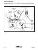
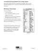
Printer Overview Depending on the options you have selected, your printer may look slightly different.
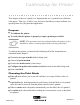
Calibrating the Printer This chapter of the user’s guide is so important that we’ve printed it on a different color paper! That way, it will be easy for you to find when you must calibrate (set up) the printer for your particular application. Purpose � To calibrate the printer. � To verify that the printer is properly set up by printing a test label. NOTE: This procedure must be performed when the printer is first installed or when it cannot properly detect the top of the label.
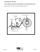
Loading the Media Figure 6 illustrates one method of media loading. For more detailed instructions, as well as information about how to load the different types of media and the various printing modes, refer to the instructions that begin on page 22.
Positioning the Media Sensor The correct positioning of the media sensor is important. It can make the difference between a perfect label and a call to Technical Support! There are two media sensors in this printer: “reflective” and “transmissive.” Reflective Sensor The reflective sensor detects the “start-of-label indicator” (the notch, hole, black mark, or gap between die-cut labels).
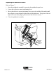
Adjusting the Reflective Sensor Refer to Figure 7. 1. Open the printhead assembly by pressing the printhead open lever. 2. Locate the reflective sensor positioning lever. 3. Move the reflective sensor positioning lever across the width of the media until the reflective sensor aligns with the start-of-label indicator. The glow of the red light will assist in the proper placement of the reflective sensor. 4. Close the printhead assembly.
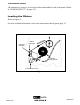
Transmissive Sensor The transmissive sensor is in a fixed position and enabled via the front panel (details in “SENSOR SELECT” on page 41). Loading the Ribbon Refer to Figure 8. For more detailed information, refer to the instructions that begin on page 34.
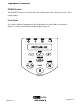
Operator Controls POWER Switch The POWER switch is located at the back of the printer above the power cord. Turn on the printer. Front Panel For a more detailed explanation of the front panel keys and lights (as shown in Figure 9), refer to the instructions that begin on page 19.
Configuring the Printer The configuration procedure in the next table contains the information you need to get your printer up and running, but it is not comprehensive. Refer to page 40 for more information. � Press the SETUP/EXIT key at the “PRINTER READY” display to enter the configuration mode. NOTE: You will need to press the INCREMENT (+) key more than once to advance to some of the displays. � Press the INCREMENT (+) or DECREMENT (-) key to scroll to the setting you wish to change.
Configuring the Software of Printer Driver Many printer settings may also be controlled by your printer’s driver or label preparation software. Refer to the driver or software documentation for more information. Printing a Test Label To print a test label: 1. Turn off the printer. 2. Press and hold the CANCEL key while turning on the printer. 3. Release the key after the DATA light turns off (approximately five seconds).
Establishing Communication System Considerations Interfaces The method of interfacing this printer to a data source depends on the communication options installed in the printer. The standard interfaces are an RS-232/RS-422/RS-485 serial data port and a bi-directional parallel port. The optional ZebraNet PrintServer II enables printers to be connected to 10Base-T Ethernet networks.
When communicating via the parallel port (refer to Figure 12), the previously mentioned parameters are not considered. Refer to page 46 to configure the communication parameters for the printer. The values selected must be the same as those used by the host equipment connected to the printer. Printer 36-pin male Computer PC 25-pin female For serial and parallel pinout and technical information, refer to the Appendix on page 85.
Printer Basics Front Panel This section discusses the functions of the various controls and indicators on the printer. The operator should become familiar with each of these functions. Front Panel Display The front panel display communicates operational status and programming modes and parameters.
Front Panel Keys Key FEED Function Forces the printer to feed one blank label each time the key is pressed. • Printer not printing: one blank label immediately feeds. • Printing: one blank label feeds after the current batch of labels is complete. PAUSE Starts and stops the printing process. • Printer not printing: no printing occurs. (Press PAUSE again to resume printing.) • Printing: printing stops once the current batch is complete. CANCEL When in the pause mode, this key will cancel print jobs.
Front Panel Lights Light POWER Status The printer is off or no power is applied. On The printer is on. Off Normal printer operation. On The printer has stopped all printing operations. PAUSE Flashing Off ERROR DATA Indication Off In peel-off mode, the PAUSE light flashes when the label is available for removal, and when initializing FLASH or PCMCIA memory. Normal printer operation (no errors).
Roll Media Loading Tear-Off Mode Refer to Figure 14. 1. Press the printhead open lever. The printhead assembly springs up. 2. Flip down the media supply guide. 3. Slide out the media guide as far from the printer frame as possible. 4. Place the roll of media on the media supply hanger. 5. Flip up the media supply guide. Slide in the media supply guide so that it just touches, but does not restrict, the edge of the roll. 6.
Cutter Mode (Cutter option required) Refer to Figure 15. 1. Press the printhead open lever. The printhead assembly springs up. 2. Flip down the media supply guide. 3. Slide out the media guide as far from the printer frame as possible. 4. Place the roll of media on the media supply hanger. 5. Flip up the media supply guide. Slide in the media supply guide so that it just touches, but does not restrict, the edge of the roll. 6.
Value Peel-Off Mode (Value peel option required) Refer to Figure 16. 1. Press the printhead open lever. The printhead assembly springs up. 2. Flip down the media supply guide. 3. Slide out the media guide as far from the printer frame as possible. 4. Place the roll of media on the media supply hanger. 5. Flip up the media supply guide. Slide in the media supply guide so that it just touches, but does not restrict, the edge of the roll. 6.
Power Peel-Off Mode (Power peel-off option required) Refer to Figure 17. 1. Press the printhead open lever. The printhead assembly springs up. 2. Flip down the media supply guide. 3. Slide out the media guide as far from the printer frame as possible. 4. Place the roll of media on the media supply hanger. 5. Flip up the media supply guide. Slide in the media supply guide so that it just touches, but does not restrict, the edge of the roll. 6.
Media supply guide Transmissive sensor Front housing assembly Printhead assembly Label Dancer Ribbon sensor Media guide Printhead open lever Media supply hanger Take-up spindle Rewind media guide Media alignment spindle Thumbscrew Figure 17 Backing Removal 1. Cut the backing material prior to where it winds onto the take-up spindle. 2. Rotate the take-up spindle until the rewind media guide is in the “12 o’clock” position. 3.
Power Rewind Mode (Power rewind option required) Refer to Figure 18. 1. Press the printhead open lever. The printhead assembly springs up. 2. Flip down the media supply guide. 3. Slide out the media guide as far from the printer frame as possible. 4. Place the roll of media on the media supply hanger. 5. Flip up the media supply guide. Slide in the media supply guide so that it just touches, but does not restrict, the edge of the roll. 6.
Media supply guide Transmissive sensor Front housing assembly Printhead assembly Dancer Ribbon sensor Media guide Printhead open lever Media supply hanger Take-up spindle Rewind media guide Media alignment spindle Thumbscrew Figure 18 Media Removal 1. Cut the media prior to where it winds onto the take-up spindle. 2. Rotate the take-up spindle until the rewind media guide is in the “12 o’clock” position. 3.
Fanfold Media Loading Fanfold media feeds through either the bottom or rear access slot. Refer to Figure 19. 1. Press the printhead open lever. The printhead assembly springs up. 2. Flip down the media supply guide. 3. Slide out the media guide as far from the printer frame as possible. 4. Pass the fanfold media over the media supply hanger. 5. Flip up the media supply guide. Slide in the media supply guide so that it just touches, but does not restrict, the edge of the media. 6.
Media supply guide Printhead assembly Transmissive sensor Dancer Ribbon Media guide sensor Printhead open lever Media supply hanger Media supply guide Printhead assembly Transmissive sensor Dancer Ribbon Media guide sensor Printhead open lever Media supply hanger Figure 19 Zebra Z4M Printer User’s Guide H-974 PAGE 24 OF 57 33 0808 IH-974
Ribbon Loading NOTE: The ribbon supply spindle in your printer is a "dual tension" variety. Most applications require the spindle to be in the "normal" position. The "low tension" position is recommended only when wide ribbon is used and normal tension hampers the ribbon movement. To place this spindle in the "normal" position, firmly pull out the spindle end cap until it clicks into place as shown in Figure 20.
Ribbon take-up spindle Printhead assembly Ribbon guide plate Ribbon supply spindle Printhead open lever Ribbon take-up spindle Printhead assembly Ribbon guide plate Ribbon supply spindle Printhead open lever Ribbon sensor Figure 21 Ribbon Removal To remove the ribbon: Zebra Z4M Printer User’s Guide 35 1. Break the ribbon between the ribbon guide plate and the ribbon take-up spindle. 2.
Configuration After you have installed the media and ribbon and the power-on self test (POST) is complete, the front panel display will show “PRINTER READY.” (If the printer fails its POST, refer to page 73.) You may now set printer parameters for your application using the front panel display and the four keys directly below it. NOTE: Printers that are operating on an IP network can be quickly configured via ZebraNet WebView™ (optional ZebraNet PrintServer II required).
Changing Password-Protected Parameters Certain parameters are password protected by factory default. NOTE: You have the option of making ALL parameters password protected. See “PASSWORD LEVEL” on page 52. CAUTION: Do not change password-protected parameters unless you are sure you know what you are doing! If they are set incorrectly, these parameters could cause the printer to function in an unpredictable way.
Leaving the Setup Mode You can leave the program mode at any time by pressing the SETUP/EXIT key. The “SAVE CHANGES” display will appear. There are five choices, described below. Pressing the INCREMENT (+) or DECREMENT (-) key displays other choices and pressing the SELECT key selects the displayed choice. � PERMANENT -- Permanently saves the changes. Values are stored in the printer even when power is turned off. � TEMPORARY -- Saves the changes until changed again or until power is turned off.
Display Shows Action/Explanation PRINT MODE Selecting Print Mode Press the INCREMENT (+) or DECREMENT (-) key to display other choices. Default: Tear-off Selections: Tear-off, peel-off, cutter, rewind Print mode settings tell the printer the method of media delivery that you wish to use. Be sure to select a print mode that your hardware configuration supports since some selections displayed are for optional printer features.
Display Shows Action/Explanation INITIALIZE CARD Initialize Memory Card CAUTION: Perform this operation only when it is necessary to erase all previously stored information from the optional memory card. Press the SETUP/EXIT key to bypass this function. 1. Press the INCREMENT (+) key to select “YES.” If your printer is set to require a password, you will now be prompted to enter the password. Enter the password and then press the SELECT key. 2. The display will ask “INITIALIZE CARD?”.
Figure 22 Setting Communication Parameters Communication parameters must be set correctly for the printer to communicate with the host. These parameters make sure that the printer and host are “speaking the same language.” All communication parameters are password protected. Display Shows Action/Explanation Setting Parallel Communications Press the INCREMENT (+) or DECREMENT (-) key to display other choices.
Display Shows Action/Explanation PARITY Setting Parity Press the INCREMENT (+) or DECREMENT (-) key to display other choices. Default: Even Selections: Even, odd, none The parity of the printer must match the parity of the host for accurate communications to take place. Select the parity that matches the one being used by the host. Setting Host Handshake Press the INCREMENT (+) or DECREMENT (-) key to display other choices.
Selecting Prefix and Delimiter Characters Prefix and delimiter characters are 2-digit hex values used within the ZPL/ZPL II formats sent to the printer. The printer uses the last prefix and delimiter characters sent to it, whether from a ZPL II instruction or from the front panel. NOTE: DO NOT use the same hex value for the control, format, and delimiter character. The printer needs to see different characters to function properly.
Selecting ZPL Mode Display Shows Action/Explanation ZPL MODE Selecting ZPL Mode Press the INCREMENT (+) or DECREMENT (-) key to display other choices. Default: ZPL II Selections: ZPL II, ZPL The printer will remain in the selected mode until it is changed by this front panel instruction or by using a ZPL/ZPL II command. The printer accepts label formats written in either ZPL or ZPL II. This eliminates the need to rewrite any ZPL formats you already have.
Label Positioning Parameters Display Shows Action/Explanation BACKFEED Backfeed Sequence Press the INCREMENT (+) or DECREMENT (-) key to display other choices. Default: Default (90%) Selections: Default, after, before, 10%, 20%, 30%, 40%, 50%, 60%, 70%, 80%, off This parameter establishes when and how much label backfeed occurs after a label is removed or cut in the peel-off or cutter modes. It has no effect in rewind or tear-off modes.
Display Shows Action/Explanation WEB S. MEDIA S. RIBBON S. TAKE LABEL S. MEDIA LED These parameters are automatically set during the calibration procedure. They should only be changed by a qualified service technician. Refer to the maintenance manual for more information on these parameters. Press the SELECT key repeatedly to skip these parameters.
Display Shows Action/Explanation IP RESOLUTION* IP Resolution Press the INCREMENT (+) or DECREMENT (-) key to display other choices. Default: Dynamic Selections: Dynamic, permanent Depending on the selection, allows either the user (”permanent”) or the server (”dynamic”) to select the IP address. For more information, refer to ZebraNet Networking: PrintServer II Installation and User’s Guide. IP PROTOCOLS* IP Protocols Press the INCREMENT (+) or DECREMENT (-) key to display other choices.
Listing Printer Information Display Shows Action/Explanation LIST FONTS List Fonts Press the INCREMENT (+) key to print a label listing all of the available fonts. This selection is used to print a label that lists all of the fonts currently available in the printer, including standard printer fonts plus any optional fonts. Fonts may be stored in RAM, FLASH memory, font EPROMs, or font cards.
Display Shows Action/Explanation LANGUAGE Selecting the Display Language Press the INCREMENT (+) or DECREMENT (-) key to display other choices. Default: English Selections: English, Spanish, French, German, Italian, Norwegian, Portuguese, Swedish, Danish, Spanish 2, Dutch, Finnish, Japan This parameter allows you to change the language used on the front panel display. You have now completed the entire configuration and calibration sequence. You may either press the SELECT key or the SETUP/EXIT key.
Routine Care and Adjustments Cleaning This table provides a recommended cleaning schedule. Specific cleaning procedures are provided on the following pages. Area Method Printhead Solvent* Platen roller Solvent* Media sensors Air blow Ribbon sensor Air blow Media path Solvent* Ribbon path Solvent* Pinch roller (Optional value peel-off option required. See Figure 25.) Solvent* Interval After every roll of media (or 500 feet of fanfold media) when printing in the direct thermal mode.
Cleaning the Exterior The exterior surfaces of the printer may be cleaned with a lint-free cloth. Do not use harsh or abrasive cleaning agents or solvents. If necessary, a mild detergent or desktop cleaner may be used sparingly. Cleaning the Interior Remove any accumulated dirt and lint from the interior of the printer using a soft bristle brush and/or vacuum cleaner.
NOTE: If print quality has not improved after performing this procedure, try cleaning the printhead with Save-a-Printhead cleaning film. This specially coated material removes contamination buildup without damaging the printhead. Call your authorized Zebra reseller for more information. Printhead assembly Take label sensor Transmissive sensor Ribbon sensor Reflective sensor Platen roller Figure 23 Cleaning the Sensors Brush or vacuum any accumulated paper lint and dust away from the printer sensors.
Cleaning the Power Peel-Off Module (Power peel-off option required) Perform the following procedure if adhesive buildup begins to affect peel performance. Refer to Figure 24. 1. Open the printhead assembly. 2. Open the front housing assembly by lifting the two handles; then, pivot down the front housing assembly. 3. Remove the accumulated adhesive by rolling the sticky side of a blank label against the peel rollers and lifting it away. (Do this step repeatedly until a majority of the adhesive is gone.
Cleaning the Value Peel-Off Module (Value peel-off option required) Perform the following procedure if adhesive buildup begins to affect peel-off performance. Refer to Figure 25. 1. Open the printhead assembly. 2. Open the pivot bracket assembly by pivoting the module toward you. 3. Use a swab soaked with the Zebra-recommended solvent to remove adhesive from the tear-off/peel-off bar. 4. Manually rotate the pinch roller and clean thoroughly with solvent and a swab. 5.
Cleaning the Cutter Module (Cutter option required) WARNING!!! For personnel safety, ALWAYS turn off and unplug the printer before performing this procedure. Refer to Figure 26. To clean adhesive off of the upper and lower cutter blades: 1. Use a swab moistened with the Zebra-recommended solvent to wipe along the upper cutter blade. 2. To expose the lower cutter blade, turn the cutter motor thumbnut counterclockwise until you see the “V”-shaped lower cutter blade. 3.
Upper cutter blade Lower cutter blade Cutter motor thumbnut Figure 26 Lubrication CAUTION! No lubricating agents of any kind should be used on this printer! Some commercially available lubricants will damage the finish and the mechanical parts, if used.
Printhead Pressure Adjustment This adjustment may be necessary if printing is too light on one side or if thick media is used. Refer to Figure 27. The pressure adjustment dials each have four possible settings designated by blocks of increasing size embossed on the print mechanism. The smallest block (fully counterclockwise) is considered “position 1” and the largest block (fully clockwise) is considered “position 4.” The following table will help you to select the initial dial settings for your media.
Pressure adjustment dials Figure 27 Power Rewind Media Alignment (Power rewind option required.) NOTE: Under normal operating conditions, media alignment should not be necessary if the media/backing was initially installed tightly against the backplate of the take-up spindle. Perform the following adjustment if the media does not track properly onto the take-up spindle. Refer to Figure 28. 1. With media and backing material loaded, open the printhead assembly. 2.
Printhead assembly Take-up spindle Adjustment dial Figure 28 Fuse Replacement A user-replaceable AC power fuse is located just below the AC power switch at the rear of the printer. The replacement fuse is a 3AG fast blow style rated at 5 Amp/250 VAC. Before replacing the fuse, turn off the AC power switch and unplug the AC power cord. To replace the fuse, insert the tip of a flat blade screwdriver into the slot in the end of the fuse holder end cap.
Troubleshooting LCD Error Conditions and Warnings Error condition RIBBON OUT Problem Solution In thermal transfer mode, the ribbon is not loaded or loaded incorrectly. Load the ribbon correctly. See “Ribbon Loading” on page 34. In thermal transfer mode, the ribbon sensor is not sensing correctly loaded ribbon. Perform the media and ribbon sensor calibration (see page 45).
Error condition HEAD OPEN Problem Solution The printhead is not fully closed. Close the printhead. The ribbon is loaded incorrectly; it is covering the head open sensor. Correctly align the ribbon with the guide mark on the ribbon guide plate before closing the printhead assembly. See “Ribbon Loading” on page 34. Error condition RIBBON IN Problem Solution Print method is incorrectly set. Via the front panel, locate the “PRINT METHOD” menu item (page 42) and select thermal transfer mode.
Error condition HEAD OPEN Problem Solution The printhead is not fully closed. Close the printhead. The ribbon is loaded incorrectly; it is covering the head open sensor. Correctly align the ribbon with the guide mark on the ribbon guide plate before closing the printhead assembly. See “Ribbon Loading” on page 34. Error condition RIBBON IN Problem Solution Print method is incorrectly set. Via the front panel, locate the “PRINT METHOD” menu item (page 42) and select thermal transfer mode.
Warning CUTTER JAM Problem Cutter blade is in the media path. Solution Turn off the printer power and unplug the printer. Inspect the cutter module for debris and clean as needed following the cleaning instructions on page 60. OUT OF MEMORY* Problem Solution Insufficient DRAM for the label length, downloaded fonts/graphics, and images. *There is not enough memory to perform the function shown on the second line of the error message.
Gray lines on blank labels with no consistent pattern Problem Solution Clean the printhead according to the instructions on page 56. The printhead is dirty. Light, consistent vertical lines running through all of the labels Problem The printhead or platen roller is dirty. Solution Clean the printhead, platen roller, or both according to the instructions on page 56. Intermittent creases on the left and right edges of the label Problem There is too much pressure on the printhead.
Calibration Problem Solution Adjust the reflective sensor position. See page 11. Set the printer for the correct media type. See page 41. Ensure that the media guides are properly positioned. Loss of printing registration on labels. Excessive vertical drift in top-of-form registration. Via the front panel, locate the “SENSOR SELECT” menu item (page 41) and manually select the correct sensing method. Reload the media. Check the reflective sensor position (see page 11).
A label format was sent to the printer. Several labels print, then the printer skips, misplaces, misses, or distorts the image on the label. Problem The host is set to EPP parallel communications. The serial communication settings are incorrect. Solution Change the settings on the computer host to standard parallel communications. Check the communication cable length. See page 18 for requirements. Check the printer driver or software communications settings (if applicable).