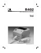
R402 Smart Label Printer and Encoder User's Guide 980389-001 Rev.
Proprietary Statement This manual contains proprietary information of Zebra Technologies Corporation. It is intended solely for the information and use of parties operating and maintaining the equipment described herein. Such proprietary information may not be used, reproduced, or disclosed to any other parties for any other purpose without the expressed written permission of Zebra Technologies Corporation.
Contents Introduction Hello! . . . . . . . . . . . . . . . . . . . . . . . . . . . . . . . . . . . . . . . . . . . . . . . . . . . . . 1 What’s in the Box?. . . . . . . . . . . . . . . . . . . . . . . . . . . . . . . . . . . . . . . . . . . 2 Inspecting the Printer . . . . . . . . . . . . . . . . . . . . . . . . . . . . . . . . . . . . . . . . . 3 Opening the printer . . . . . . . . . . . . . . . . . . . . . . . . . . . . . . . . . . . . . . . 3 Closing the printer . . . . . . . . . . . . . . . . . . . . .
Operation & Options Thermal Printing . . . . . . . . . . . . . . . . . . . . . . . . . . . . . . . . . . . . . . . . . . . 19 Replacing Supplies. . . . . . . . . . . . . . . . . . . . . . . . . . . . . . . . . . . . . . . . . . 20 Adding a New Transfer Ribbon . . . . . . . . . . . . . . . . . . . . . . . . . . . . 20 Replacing a Partially Used Transfer Ribbon . . . . . . . . . . . . . . . . . . . 20 Printing in Peel-Mode . . . . . . . . . . . . . . . . . . . . . . . . . . . . . . . . . . . . . . .
Resetting the Factory Default Values . . . . . . . . . . . . . . . . . . . . . . . . . 51 Communications Diagnostics . . . . . . . . . . . . . . . . . . . . . . . . . . . . . . . . . 51 Feed Button Modes . . . . . . . . . . . . . . . . . . . . . . . . . . . . . . . . . . . . . . . .
980389-001 Rev.
Introduction This section describes what you get in your shipping box and provides an overview of printer parts. This section also has procedures that describe how to open and close the printer and report any problems. Hello! ® ™ Thank you for choosing the Zebra R402 Printer, a high-quality thermal transfer on-demand printer with RFID capability manufactured by the industry leader in quality, service, and value—Zebra Technologies Corporation.
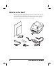
What’s in the Box? Save the carton and all packing materials in case you need to ship or store the printer later. After unpacking, make sure you have all parts. Follow the procedures for inspecting the printer to familiarize yourself with printer parts so you can follow the instructions in this book.
Inspecting the Printer Look at the outside of the printer and make sure that all parts are present. Opening the printer To access the media compartment, you must open the printer. Pull the release levers towards you and lift the cover.
INSPECTING THE PRINTER (continued) After opening the printer, check the media compartment.
Closing the printer Hold the top cover and press the cover lock to release. Lower the top cover. The ribbon carriage automatically folds up into place. Press down until the cover snaps closed.
Reporting Damage If you discover damage or missing parts: ■ Immediately notify and file a damage report with the shipping company. Zebra Technologies Corporation is not responsible for any damage incurred during shipment of the printer and will not cover the repair of this damage under its warranty policy. ■ Keep the carton and all packing material for inspection.
Getting Started This section describes how to set up your printer for the first time and use the most common operating procedures for loading media in tear-off mode and loading ribbon. Modes of Printing You can operate this printer in two different modes: tear-off or peel-off. ■ Standard tear-off mode allows you to tear off each label (or a strip of labels) after it is printed. ■ In optional peel-off mode, the backing material is peeled away from the label as it is printed.
Attaching Power Supply Check the power supply to make certain it is appropriate for your input voltage. Warning: Use the Zebra-supplied power supply that came with your printer. Never operate the printer and power supply in an area where they can get wet. Serious personal injury could result! 1. Make sure the power switch is in the off position (down). 2. The DC power supply has a barrel connector on one end that must be inserted into the power supply receptacle on the back of the printer. 3.
Loading Roll Media When you load media, you must place the roll on the media hangers and then adjust the media guides. Placing the Roll in the Media Compartment Whether your roll media is inside or outside wound you load it into the printer the same way. 1. Open the printer. Remember that you need to pull the release levers toward the front of the printer. 2. Remove the outside length of media. During shipment, the roll may become dirty when handled or dusty when stored.
Adjusting the Guides The adjustable guides direct the media toward the platen and print head. 1. Open the media guides by turning the guide adjuster knob to the rear. 2. Thread the media through the guides. 3. Close the media guides by turning the guide adjuster knob to the front. They should just touch, but not restrict, the edges of the media. 4. Unless you need to load ribbon, close the top cover.
Using the Optional Media Adapter Plates If your media roll has a larger diameter core, you can use an accessory (part number 105810-002) to adapt the core to the media holders. 1. Note which position will fit the diameter of the roll core. 2. On the left side plate, align the pegs with the screws and use a small Phillips driver to tighten them. 3. On the right side plate, align the pegs with the screws and use a small Phillips driver to tighten them. 4.
Loading Ribbon You must use thermal transfer media (accepts wax and/or resin transferred off a ribbon) when you use a ribbon. When loading ribbon, you install the supply and take-up rolls, then tighten the ribbon on the carriage. Install the Ribbon Supply Roll Before following these steps, prepare the ribbon by removing its wrapping and pulling its adhesive strip free. 1. Thread the ribbon through the carriage. 2. Press the right side onto the supply hub. 3.
Attach and Tighten the Ribbon You must align the ribbon so that it will be taken straight onto the core. 1. Attach the ribbon to the take up core. Use the adhesive strip on new rolls; otherwise, use tape. 2. Turn the ribbon take-up gear counter-clockwise (top moves toward rear) to remove slack from the ribbon. 3. Close the top cover. Remember that you need to release the cover lock, lower the top cover, and press down until the latches snap into place.
Auto Calibration NOTE: If you are using pre-printed labels, pre-printed label backing, or continuous media, see “Manual Calibration” on page 49. An auto calibration is performed when the printer is turned on (if media is loaded) or after a media error is cleared. When it is auto calibrating, the printer sets the sensor levels for, and determines the length of, the label you are using. If the status light flashes red, refer to “Manual Calibration” on page 49.
Operator Controls Power Switch Press up to turn ON or down to turn OFF the printer. CAUTION: The power should be turned off before connecting or disconnecting the communications and power cables. Feed Button Forces the printer to feed one blank label. Takes the printer out of a “pause” condition. (The printer is put into “pause” by either a ZPL II command or an error condition.) See “What the Status Light is Telling You” on page 43.
Printing a Test Label Before you connect the printer to your computer, make sure that the printer is in proper working order. You can do this by printing a configuration label. 1. Make sure the media is properly loaded and the top cover of the printer is closed. Then, turn the printer power on if you have not already done so. 2. When the status light is solid green, press and hold the feed button until the status light flashes once. 3. Release the feed button. A configuration label will print.
Hooking Up the Printer and Computer This printer comes with a bidirectional parallel data interface. You must supply the required interface cable for your application. CAUTIONS:Keep the power switch in the OFF position when attaching the interface cable. The power supply barrel connector must be inserted into the power supply receptacle on the back of the printer before connecting or disconnecting the communications cables.
Communicating with the Printer When using the parallel port, typically there is no setup is required once the cable is plugged in. If you should encounter any problems, consult the user’s guide that came with your computer. Adjusting the Print Width Print width must be calibrated when: ■ You are using the printer for the first time. ■ There is a change in the width of the media.
Operation & Options This section helps you get the most from your printer. You must use programming to control many of the printer’s functions. A few examples: ■ The ~JL command controls label length. ■ The ^XA^MTD^XZ command changes the printing mode to direct thermal; the ^XA^MTT^XZ command changes the printing mode to thermal transfer. ■ The ^XA^JUS^XZ command saves the new settings to flash memory.
Replacing Supplies If labels or ribbon run out while printing, leave the printer power on while reloading (data loss results if you turn off the printer). After you load a new label or ribbon roll, the printer flashes double-green until you press the Feed button to restart . Always use high quality, approved labels, tags and ribbons.
Printing in Peel-Mode ON OFF The optional dispenser allows you to print in “peel-mode” where the label backing follows a different path and the labels are presented one at a time for subsequent placement. Before using peel-mode, you must send the programming commands ^XA ^MMP ^XZ ^XA ^JUS ^XZ to the printer. Refer to your ZPL II Programmer’s Manual. 1. Remove several labels from the backing material. 2. Open the top cover. 3. Open the dispenser door. 4. Switch on the label-taken sensor. 5.
Printing on Fan-Fold Media Printing on fan-fold media requires you to set both the media hangers and the media guides in position. Lock-down Screw 1. Open the top cover. 2. With a sample of your media, adjust the media hangers to the width of the media. The hangers should just touch, but not restrict, the edges of the media. 3. Tighten the screw using a small Phillips driver #1. 4. With a sample of your media, adjust the guides to the width of the media.
RFID Guidelines The Zebra R402 Smart Label Printer and Encoder serves as dynamic tool for both printing and programming smart labels, tickets and tags. Smart labels are usually made from two components, media and a RFID (radio frequency identification) transponder. The media will usually be comprised of synthetic- or paper-based material that can be printed upon using direct thermal or thermal transfer printing techniques.
The communication between the RFID tag and R402 printer is established when the transponder lines up with the printer’s antenna. Note that transponder position, prior to encode/decode, is critical. The optimal transponder position varies with antenna coil size and type of RFID IC used. It is important to use media and tags that have been specifically designed for use in the R402. Failure to do so may result in the inability to read or program the embedded RFID tags.
Texas Instruments Tag-it™ Transponders Texas Instruments transponders are high frequency (13.56MHz) RFID devices. Each transponder has 256 bits of memory. Data is segmented into 4 byte (32 bit) blocks that are uniquely addressable, for a total of 8 blocks. Each memory block is lockable using the write protect function during the writing process.
Philips I•Code Transponders Philips I•Code transponders are high frequency (13.56MHz) RFID devices. Each transponder has 512 bits of memory. Data is segmented into 4 byte (32 bit) blocks that are uniquely addressable for a total of 16 blocks. Each memory block is lockable using the write protect function during the writing process. The first two blocks of data (block 0 and 1) are pre-programmed, non-changeable, and are used for storage of a unique 64 bit serial number.
Inside Technologies Picotag® Transponders Inside Technologies Picotag® transponders are high frequency (13.56MHz) RFID devices. Each transponder has 2048 bits of memory. Data is segmented into 8 byte (64 bit) blocks that are uniquely addressable for a total of 31 blocks. Blocks 6 to 12 are lockable using the write protect function during the writing process. The first block of data (block 0) is pre-programmed and is used for storage of a unique 64 bit serial number.
ISO-15693 Transponders ISO-15693 is an international standard for 13.56 MHz RFID devices. As this is a public standard, tags and integrated circuits may be produced by a wide variety of manufacturers. The current standard stipulates that manufacturers may configure memory in various ways ( up to 256 blocks comprising a block size up to 256 bits (32 bytes)).
ZPL II Commands for RFID ^WT – Write Tag The format for the ^WT instruction is: ^WTb,r,m,w,s where ^WT = Write Tag command b = Block Number Default value: 0 Other values: 1 to n, where n is the maximum number of blocks for the tag This is the starting block number. If the user sends more than a block of data it will overflow into the next block. If the user overflows the block and subsequent blocks cause errors (write protects, beyond range, etc.
^RT – Read Tag The format for the ^RT instruction is: ^RT#,b,n,f,r,m,s where ^RT = Read Tag command # = Number to be assigned to the Field Default value: 0 Other Values: 1 to 9999 b = Starting Block Number Default value: 0 Other values: 1 to n, where n is the maximum number of blocks for the tag n = Number of blocks to read Default value: 1 Other values: 2 to n, where n is maximum number of blocks minus starting block number.
^RT – Read Tag (continued) Example: This reads a block from a tag, and prints it on a label: ^XA ^FO20,120^A0N,60^FN1^FS ^FO20,100^A0N,20^FN2^FS ^RT1,0,7,3,0,5,0,0^FS ^RT2,0,2,2,0,5,0,0^FS ^XZ The first ^RT command automatically detects the tag type, starting at block 7, reads three blocks of data in ASCII format. It will retry the command 5 times if necessary. A “void” label will be generated if the read is unsuccessful after ‘r’ retries.
^RS – RFID Setup The format for the ^RS instruction is: ^RSt,# where t = tag type Default value: 0 –NONE (No tags available) Other values: 1- Auto detect (automatically determine the tag type, by querying the tag) 2- Texas Instruments Tag-it™ tags 3- Philips I•Code tags 4- Inside Technologies Picotag® 2K 5- ISO 15693 tag* # = read/write position of transponder in rows of dots Set to 0 (zero) to not move the media.
^RI – RFID Get Tag Unique ID The format for the ^RI instruction is: ^RIn where n = field number to store the unique ID The unique ID will be read from the tag and available to print or return to the host computer.
Sample of RFID Programming TM ZPL II is Zebra Technologies Corporation’s Zebra Programming Language II label design language. ZPL II lets you create a wide variety of labels from the simple to the very complex, including text, bar codes, and graphics. This section is not intended as an introduction to ZPL II. If you are a new ZPL II user, order a copy of the ZPL II Programming Guide (part# 46530L) or go to the internet address http://support.zebra.
Line # Type this label format 1. ^XA 2. ^WT6^FDZebra^FS 3. ^FO100,100^A0n,60^FN0^FS 4. ^FO100,200^A0n,40^FN1^FS 5. ^RT0,6,2^FS 6. ^RT1,6,2,1 7. ^XZ Resulting printout ZEBRA 5A65627261000000 Line 1 Indicates start of label format. Line 2 Writes the data “Zebra” to block 6 for the tag (one byte will spill into block 7, since we have 4 bytes/block. Line 3 Print field number ‘0’ at location 100,100.^FN0 is replaced by what we read on line #5. Line 4 Print field number ‘1’ at location 100,200.
Maintenance Cleaning Use only the cleaning agents indicated. Zebra Technologies Corporation will not be responsible for damage caused by any other cleaning materials used on this printer. Printer Part Method Interval After allowing the print head to cool for approximately one minute, use 70% isopropyl alcohol on a cotton swab to clean the print elements from end to end (the print elements are located in the thin gray line on the print head). NOTE: You do not have to turn off the printer to do this.
Parts List DESCRIPTION PART NUMBER 1 Latch Assembly 105910-052 2 Feed Switch/Sensor Assy (set of 3) 105910-128 3 Upper Cover Support (set of 3) 105910-066 4 Print Head Assy - 4” TLP Print Head Cable Assy.
1 15 2 14 3 13 4 5 6 12 8 7 11 9 10
Replacing the Print Head In the event you need to replace the print head, make sure your work area is prepared by protecting against static discharge. Your work area must be static-safe and include a properly grounded conductive cushioned mat to hold the printer a conductive wrist strap for yourself. Removal Before following the steps in this procedure, open the printer by pulling the release latches forward then lifting the top cover. Remove any ribbon from the carriage. 1.
REPLACING THE PRINT HEAD (Continued) Assembly The new print head comes with the clip and ground screw attached. 1. Align the print head and bracket to plug the left and right connectors into the black and white wire bundles. 2. Attach the ground wire and secure it with the screw. Use a #2 Phillips driver to tighten it. 3. Insert the bracket pegs into the left side of the carriage. Cleaning the Print Head 4.
Troubleshooting What the Status Light is Telling You Status LED Condition and Color Printer Status For a Resolution, Refer to number: Off Off 1 Solid Green On 2 Flashing Yellow Stopped 3 Flashing Green Normal Operation 4 Flashing Red Stopped 5 Double Flashing Green Paused 6 Solid Yellow Various 7 Alternately Flashing Green and Red Needs Service 8 Resolutions 1. The printer is not receiving power.
3. The printer has failed its power on self test (POST). ■ If this error occurs right after you turn on the printer, contact an authorized reseller for assistance. There is a shortage of memory. ■ If this error occurs after you have been printing, turn the printer power off and on. Then, resume printing. 4. The printer is receiving data. ■ As soon as all of the data has been received, the status LED will turn green; then, the printer will automatically resume operation. 5.
7. The print head is under temperature. ■ Continue printing while the print head reaches the correct operating temperature. The print head is over temperature. ■ Printing will stop until the print head cools to an acceptable printing temperature. When it does, the printer will automatically resume operation. 8. FLASH memory is not programmed. ■ Return the printer to an authorized reseller.
Print Quality Problems No print on the label. ■ You must use the correct media for the method of printing you require. When printing without a ribbon, you must use direct thermal media. When using ribbon, you must use thermal transfer media. The printer's ribbon sensor detects motion of the supply spindle. ■ Is the media loaded correctly? Follow the instructions in “Loading the Media” on page 9. The printed image does not look right. ■ The print head is dirty.
The printing does not start at the top of the label, or misprinting of one to three labels. ■ The media may not be threaded under the media guides. Refer to “Loading the Media” on page 9. ■ The printer needs to be calibrated. Refer to “Auto Calibration” on page 14. ■ The correct media sensor may not be activated. Manual calibration selects the media sensing method for the labels being used (refer to the ^MN command in the ZPL II Programming Guide).
RFID Symptoms RFID tags generally not programmed ■ Is the printer set up correctly? Print a configuration label to verify RFID version. See “Auto Calibration” on page 14. ■ Check if supported RFID media is loaded correctly. VOID messages are printed across media. ■ Verify tag type is properly selected in ZPL II. Use RFID media with supported tag type. Edit ZPL II to select proper tag type or increase retries. ■ ZPL II is attempting to write to a non-existent block.
Manual Calibration Manual calibration is recommended whenever you are using pre-printed labels (or label backing) or if the printer will not correctly auto calibrate. 1. Turn on the printer power. 2. Remove approximately 4" (102 mm) of labels from a section of backing material. Load the media so that only the backing material is threaded through the printer and under the print head. 3. Press and hold the feed button until the green status LED flashes once, then twice. Release the feed button. 4.
Troubleshooting Tests Printing a Configuration Label To print out a listing of the printer’s current configuration, refer to the one-flash sequence in “Feed Button Modes” on page 52. Recalibration Recalibrate the printer if it starts to display unusual symptoms, such as skipping labels. See “Auto Calibration” on page 14. PRI NTER CONFI GURATI ON Zebr a Tec hnol ogi es ZTC R402- 200dpi +10 . . . . . . . . . . . . +000 . . . . . . . . . . . TEAR OFF. . . . . . . NON- CONTI NUOUS. WEB. . . . . . . . . . . .
Resetting the Factory Default Values Sometimes, resetting the printer to the factory defaults solves some of the problems. Follow the four-flash sequence instructions in “Feed Button Modes” on page 52. Communications Diagnostics If there is a problem transferring data between the computer and printer, try putting the printer in the communications diagnostics mode.
Feed Button Modes Power Off Mode (Communications Diagnostics Mode) With the printer power off, press and hold the feed button while you turn on the power. The printer prints out a listing of its current configuration (see Figure 22). After printing the label, the printer will automatically enter a diagnostic mode in which the printer prints out a literal representation (see Figure 23) of all data subsequently received. To exit the diagnostic mode and resume printing, turn off and then turn on the printer.
Appendix All specifications are subject to change without notice. Physical Specifications Size 7.8 inches wide / 6.8 inches tall / 9.4 inches long (depth) 200 mm wide / 173 mm tall / 240 mm long (depth) Weight 3.6 pounds / 1.6 kilograms Environmental Guidelines Operating temp. 40 to 104 degrees Fahrenheit / 5 to 40 degrees Celsius Operating humidity 10 to 90 percent non-condensing Storage temp.
Media Specifications Width 1 to 4.25 inches / 25.4 to 108 millimeters) 1 to 2.25 inches / 25.4 to 57 millimeters (tag stock) Length 0.5 to 22 inches / 13 to 559 millimeters with standard memory Gap 0.08 to 0.16 inch (2.0 to 4.0 millimeters) 0.118 inch / 3.0 millimeters recommended Thickness 0.003 to 0.007 inch / 0.08 to 0.18 millimeter Roll Size Maximum outer diameter: 5 inches (127 millimeters Inner Core diameters: 1 or 1.5 inches (25.
Font/Code Specifications Fonts ✔ CG Triumvirate Bold Condensed scalable smooth (0) ✔ Zebra fonts A-H, GS, P-V ✔ IBM Code Page 850 international Symbols 1D Bar Codes ✔ Codabar (supports ratios of 2:1 to 3:1) ✔ Code 11 ✔ Code 128/USD 8 (supports serialization in all subsets and UCC Case Codes) ✔ Code 39 (supports ratios of 2:1 to 3:1) ✔ Code 93 ✔ EAN 8/JAN 8 ✔ EAN 13/JAN 13 ✔ EAN 14/UPC-A ✔ Industrial 2 of 5 ✔ Standard 2 of 5 ✔ Interleaved 2 of 5 (supports ratios of 2:1 to 3:1, Modulus 10 Check Digit) ✔ L
Agency Approvals The Thermal Printer Model R402, manufactured by Zebra Technologies Corporation, complies with the applicable requirements: ✔ Emissions and susceptibility: FCC 15.225, FCC Part 15 Class B, RSS-210, EN300-330, EN300-683, IECS-003, EN61000-3-2, EN61000-3-3. ✔ Safety: UL 1950 3rd Ed., CSA C22.2 No. 950-95 3rd Ed.
Parallel Interface Technical Information Pin No. Description 1 NStrobe/Host Clk 2-9 Data Bits 1-8 10 nACK/PtrClk 11 Busy/Per Busy 12 PError/ACK Dat Req. 13 Select/Xflag 14 NAuto Fd/Host Busy 15 Not Used 16-17 Ground 18 +5 V @ 0.75 A Fused 19-30 Ground 31 nInit 32 NFault/nData Avail. 33-34 Not Used 35 +5 V throught 1.8 K Ohms Resistor 36 NSelectin/1284 active The maximum current available through the interface port is not to exceed a total of 0.75 amps.
Index A adapter plates . . . . . . . . . . . . . . . . . . . 11 agencies . . . . . . . . . . . . . . . . . . . . . . . 56 attaching power . . . . . . . . . . . . . . . . . . 8 auto calibration . . . . . . . . . . . . . . . . . . 14 B bar codes. . . . . . . . . . . . . . . . . . . . . . . 55 barrel connector . . . . . . . . . . . . . . . . . . 8 box, contents. . . . . . . . . . . . . . . . . . . . . 2 button, feed. . . . . . . . . . . . . . . . . . . . . 15 C cable . . . . . . . . . . . . . . . . . . . . . .
lubrication. . . . . . . . . . . . . . . . . . . . . . 37 M maintenance . . . . . . . . . . . . . . . . . . . . 37 manual calibration . . . . . . . . . . . . . . . 49 media . . . . . . . . . . . . . . . . . . . . . . . . . 22 media adapters . . . . . . . . . . . . . . . . . . 11 media guides. . . . . . . . . . . . . . . . . . 4, 10 media specifications . . . . . . . . . . . . . . 54 media, loading . . . . . . . . . . . . . . . . . . . 9 media, outside length . . . . . . . . . . . . . . 9 O opening . . . . .
thermal printing . . . . . . . . . . . . . . . . . 19 thermal transfer. . . . . . . . . . . . . . . . . . 20 top cover, closing . . . . . . . . . . . . . . . . . 5 top cover, opening . . . . . . . . . . . . . . . . 3 trademarks. . . . . . . . . . . . . . . . . . . . . . iii transponders . . . . . . . . . . . . . . . . . . . . 24 troubleshooting tests. . . . . . . . . . . . . . 50 U UL. . . . . . . . . . . . . . . . . . . . . . . . . . . . 56 V voltage . . . . . . . . . . . . . . . . . . . . . . . . .