T402 Stripe® Series Thermal Transfer Printer User's Guide
T402 Stripe® Series Thermal Transfer Printer User's Guide AWARDS FOR PUBLICATION EXCELLENCE Rev.
Proprietary Statement This manual contains proprietary information of Zebra Technologies Corporation. It is intended solely for the information and use of parties operating and maintaining the equipment described herein. Such proprietary information may not be used, reproduced, or disclosed to any other parties for any other purpose without the expressed written permission of Zebra Technologies Corporation.
I have determined that the Zebra printers identified as the Stripe® Series DA402 and T402 manufactured by: Zebra Technologies Corporation 333 Corporate Woods Parkway Vernon Hills, Illinois 60061-3109 U.S.A. have been shown to comply with the applicable technical standards of the FCC for Home, Office, Commercial, and Industrial use if no unauthorized change is made in the equipment, and if the equipment is properly maintained and operated.
Contents Introduction Hello! . . . . . . . . . . . . . What’s in the Box . . . . . . . Unpacking and Inspection . . . Reporting Damage . . . . . DC Power Supply . . . . . . . Printer Overview (illustration) . . . . . . . . . . . . . . . . . . . . . . . . . . . . . . . . . . . . . . . . . . . . . . . . . . . . . . . . . . . . . . . . . . . . . . . . . . . . . . . . . . . . . . . . . . . . . . . . . . . . . . . . . . . . . . . . . . . . . . . . . . . . . .
Using ZPL II . . . . . . . . . Adjusting the Print Width . . Adjusting the Print Darkness . Adjusting the Print Speed . . . . . . . . . . . . . . . . . . . . . . . . . . . . . . . . . . . . . . . . . . . . . . . . . . . . . . . . . . . . . . . . . . 30 30 30 30 Troubleshooting What the Status LED is Telling You . . . Print Quality Problems . . . . . . . . . . Manual Calibration. . . . . . . . . . . . Troubleshooting Tests . . . . . . . . . . Printing a Configuration Label . . . .
Introduction Hello! Thank you for choosing the Zebra T402 Printer. This rugged little printer is certain to become a productive and efficient addition to your workplace! n This user’s guide gives you all the information you will need to operate and maintain the printer. n To create and print label formats, take a look at the ZPL II Programming Guide (part #46530L). If one was not ordered with your printer, simply call your distributor or visit our web site at www.zebra.com.
Unpacking and Inspection Inspect the printer for possible shipping damage: Check all exterior surfaces for damage. n Raise the top cover (refer to “Loading the Media” on page 5) and inspect the media compartment for damage. In case shipping is required, save the carton and all packing material. n Reporting Damage If you discover shipping damage: n Immediately notify and file a damage report with the shipping company.
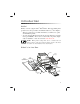
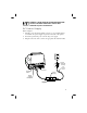
WARNING: NEVER OPERATE THE PRINTER AND POWER SUPPLY IN AN AREA WHERE THEY CAN GET WET. PERSONAL INJURY COULD RESULT! DC Power Supply Refer to Figure 1. 1. 2. 3. The DC power supply has a barrel connector on one end that must be inserted into the power supply receptacle on the back of the printer. Insert the separate AC power cord into the power supply. Plug the other end of the cord into an appropriate AC electrical outlet.
Printer Overview Feed Button Cutter Option Status LED Sensor Housing Cutter Unit Release Lever (2) Bottom Slot Media Supply Guides Ribbon Core Media Hanger Supply Spindle Tear Bar Media Guides Take-Up Spindle Peel Bar Media Guide Adjuster Printhead Release Lever Figure 2 4 Printhead Platen Roller
Getting Ready to Print Loading the Media You can operate this printer in three different modes: tear-off, peel-off, or with a cutter. n Tear-off mode allows you to tear off each label (or a strip of labels) after it is printed. n In peel-off mode, the backing material is peeled away from the label as it is printed. After this label is removed, the next one is printed. In cutter mode, the printer automatically cuts the label after it is printed.
2. 3. 4. Insert one end of the media hanger into one of the media supply guides (refer to Figure 4). Place the roll of media onto the media hanger. Place the second media supply guide onto the other end of the media hanger (refer to Figure 4). NOTES: The media roll must be centered on the media hanger. The media roll should rest against the smooth side of the media supply guides. The textured side marked “out” should face the outside of the printer.
Labels Tags Figure 5 Printhead 2 Printhead Release Lever 1 Figure 6 7
9. Refer to Figure 7. Thread the media through the media guides. NOTE: If the media guides must be changed to accommodate the width of the media, turn the green media guide adjuster (refer to Figure 7). The media guides should just touch, but not restrict, the edges of the roll. 10. 11. 12. 13. Continue to thread the media past the peel bar (refer to Figure 7). Place the media hanger into the two mounting slots (refer to Figure 8). Close the printhead by pressing down at both arrows (refer to Figure 9).
Mounting Slot Mounting Slot Figure 8 Printhead Arrow Arrow Figure 9 9
Peel-Off Mode 1. Unlatch the top cover by pressing the two green release levers (refer to Figure 10). Then, lift the top cover to expose the media compartment. 2. Insert one end of the media hanger into one of the media supply guides (refer to Figure 11). 3. Place the roll of media onto the media hanger. 4. Place the second media supply guide onto the other end of the media hanger (refer to Figure 11). NOTES: The media roll must be centered on the media hanger.
Smooth Side of Media Supply Guide Textured Side Marked "OUT" 3 2 1 Media Hanger Media Supply Guide Figure 11 Printhead 2 Printhead Release Lever 1 Figure 12 11
8. Refer to Figure 13. Thread the media through the media guides. NOTE: If the media guides must be changed to accommodate the width of the media, turn the green media guide adjuster (refer to Figure 13). The media guides should just touch, but not restrict, the edges of the media roll. 9. Continue to thread the media until it is approximately 8” (203 mm) past the peel bar (refer to Figure 13). 10. Place the media hanger into the two mounting slots (refer to Figure 14). 11. Remove approximately 6” (152.
Mounting Slot Mounting Slot Figure 14 Feed Button Bottom Slot Peel- Off Feed Slot Figure 15 13
13. Gently pull the label backing to remove any slack in the media. 14. Close the printhead by pressing down at both arrows (refer to Figure 16). 15. Close the top cover. Activate the label taken sensor by pushing in on the top of the sensor housing until it locks into position (refer to Figure 17). 16. Turn on the printer or press the feed button if the printer is already on (see “Auto Calibration” on page 25 for more information).
Printhead Arrow Arrow Figure 16 Sensor Housing Figure 17 15
Cutter Mode (optional) 1. Unlatch the top cover by pressing the two green release levers (refer to Figure 18). Then, lift the top cover to expose the media compartment. 2. Insert one end of the media hanger into one of the media supply guides (refer to Figure 19). 3. Place the roll of media onto the media hanger. 4. Place the second media supply guide onto the other end of the media hanger (refer to Figure 19). NOTES: The media roll must be centered on the media hanger.
Smooth Side of Media Supply Guide Textured Side Marked "OUT" 3 2 1 Media Supply Guide Media Hanger Figure 19 Printhead Printhead Release Lever 2 1 Figure 20 17
8. Refer to Figure 21. Thread the media through the media guides. NOTE: If the media guides must be changed to accommodate the width of the media, turn the green media guide adjuster (refer to Figure 21). The media guides should just touch, but not restrict, the edges of the roll 9. Refer to Figure 21. Thread the media through the cutter unit. 10. Place the media hanger into the two mounting slots (refer to Figure 22). 11. Close the printhead by pressing down at both arrows (refer to Figure 23). 12.
Mounting Slot Mounting Slot Figure 22 Printhead Arrow Arrow Figure 23 19
Fanfold Media Fanfold media loads from the outside of the printer. 1. 2. 3. 4. 5. Thread the media through the access slot in the back of the printer (refer to Figure 24). Open the top cover. Release the printhead by pulling the printhead release lever toward you (refer to Figure 24, “1”). Lift the printhead (refer to Figure 24, “2”) until you feel it “lock” into place. Be careful not to force the printhead past this position! Refer to Figure 25. Thread the media through the media guides.
2 Access Slot Printhead Release Lever 1 Printhead Figure 24 Media Guides Arrow Arrow Media Guide Adjuster Peel Bar Figure 25 21
Loading the Ribbon Figure 26 shows the location of the ribbon supply spindle, ribbon take-up spindle, and ribbon supply slot. 1. 2. 3. 4. 5. 6. 7. 8. 9. Open the top cover. Install an empty ribbon core (notched end to the right) as shown in Figure 27. This becomes the ribbon take-up spindle. Remove the tape that secures the leader on the new roll of ribbon. Install the ribbon roll on the ribbon supply spindle (refer to Figure 27).
Supply Spindle Ribbon Core Notch Figure 27 Take-Up Spindle Printhead Figure 28 23
10. Close the printhead by pressing down at both arrows. 11. Close the top cover and turn on the printer or press the feed button if the printer is already on (see “Auto Calibration” on page 25 for more information). Removing the Ribbon 1. Open the printhead. 2. Cut the ribbon below the ribbon take-up spindle (refer to Figure 29). 3. Remove the roll of unused ribbon. Hint: Tape the end of the ribbon to prevent the roll from unwrapping. 4. 5. Remove the ribbon take-up spindle.
Auto Calibration NOTE: If you are using pre-printed labels, pre-printed label backing, or continuous media, see “Manual Calibration” on page 34. An auto calibration is performed when the printer is turned on (if media is loaded) or after an error is cleared. When it is auto calibrating, the printer sets the sensor levels for, and determines the length of, the label you are using. If the status LED flashes red, refer to “Manual Calibration” on page 34.
Operator Controls Refer to Figure 30. Power Switch n Press to turn on and turn off the printer. CAUTION: The power should be turned off before connecting or disconnecting the communications and power cables. Feed Button n Forces the printer to feed one blank label. n When printing, puts the printer into a “pause” condition. n Takes the printer out of a “pause” condition. (The printer is put into “pause” by either a ZPL II command or an error condition.) See “What the Status LED is Telling You” on page 31.
Printing a Test Label Before you connect the printer to your computer, make sure that the printer is in proper working order. You can do this by printing a configuration label: 1. 2. 3. Make sure the media is properly loaded and the top cover of the printer is closed. Then, turn the printer power on if you have not already done so. When the status LED is solid green, press and hold the feed button until the status LED flashes once. Release the feed button. A configuration label will print.
Parallel Interface Requirements The required cable (IEEE 1284-compliant is recommended) must have a standard 36-pin parallel connector on one end, which is plugged into the parallel port located on the back of the printer (refer to Figure 31). The other end of the parallel interface cable connects to the printer connector at the host computer. For pinout information, refer to page 52.
Communicating with the Printer Via the Serial Port Serial communications between the printer and the host computer can be set by either autobaud synchronization or the ^SC command. Autobaud Autobaud synchronization allows the printer to automatically match the communications parameters of the host computer. To autobaud: 1. 2. 3. Press and hold the feed button until the green status LED flashes once, twice, then three times. While the status LED flashes, send a ZPL II format to the printer.
Using ZPL II For information about creating labels using ZPL II, refer to the ZPL II Programming Guide or visit our web site at www.zebra.com. Adjusting the Print Width Print width must be calibrated when: n n You are using the printer for the first time. There is a change in the width of the media. Print width may be set by way of the five-flash sequence in “Feed Button Modes” (see page 37) or refer to the Print Width (^PW) command (consult your ZPL II Programming Guide).
Troubleshooting What the Status LED is Telling You Status LED Condition and Color Printer Status For a Resolution, Refer to: Off Off 1 Solid Green Flashing Yellow On Stopped 2 3 Flashing Green Normal Operation 4 Flashing Red Stopped 5 Double Flashing Green Paused 6 Solid Yellow Various 7 Alternately Flashing Green and Red Needs Service 8 RESOLUTIONS: 1. The printer is not receiving power.
5. The media or ribbon is not loaded. n Load a roll of media or ribbon, following the instructions in “Loading the Media” on page 5 or “Loading the Ribbon” on page 22. Then, press the feed button to resume printing. The printhead is open. n Close the top cover. Then, press the feed button to resume printing. The cutter is jammed. n Turn off the printer and remove any jammed labels from the cutter unit. Then, turn on the printer to resume printing. 6. The printer is paused.
There are long tracks of missing print (blank vertical lines) on several labels. n n The printhead is dirty. Clean the printhead according to the instructions on page 39. The printhead elements are damaged. Replace the printhead (see “Replacing the Printhead” on page 44). The printing does not start at the top of the label, or misprinting of one to three labels. n n n n The media may not be threaded under the media guides. Refer to “Loading the Media” on page 5. The printer needs to be calibrated.
Manual Calibration A manual calibration should be performed whenever you are using pre-printed labels (or label backing) or if the printer will not correctly auto calibrate. 1. 2. 3. 4. 5. 6. 7. Turn on the printer power. Remove approximately 6” (152 mm) of labels from a section of backing material. Load the media so that only the backing material is threaded through the printer and under the printhead.
Troubleshooting Tests Printing a Configuration Label To print out a listing of the printer’s current configuration (an example is shown in Figure 33), refer to the one-flash sequence in “Feed Button Modes” on page 37. Recalibration Recalibrate the printer if it starts to display unusual symptoms, such as skipping la bels. See “Auto Calibration” on page 25.
Resetting the Factory Default Values Sometimes, resetting the printer to the factory defaults solves some of the problems. Follow the four-flash sequence instructions in “Feed Button Modes” on page 37. Communications Diagnostics If there is a problem transferring data between the computer and printer, try putting the printer in the communications diagnostics mode. The printer will print the ASCII characters and their respective hexidecimal values (see Figure 34) for any data received from the host computer.
Feed Button Modes Power Off Mode (Communications Diagnostics Mode) With the printer power off, press and hold the feed button while you turn on the power. The printer prints out a listing of its current configuration (see Figure 33). After printing the label, the printer automatically enters a diagnostic mode in which the printer prints out a literal representation (see Figure 34) of all data subsequently received. To exit the diagnostic mode and resume printing, turn off and then turn on the printer.
38
Maintenance Cleaning CAUTION: Use only the cleaning agents indicated. Zebra Technologies Corporation will not be responsible for damage caused by any other cleaning materials used on this printer. If necessary, refer to Figure 2 for part locations. Area Printhead Method After allowing the printhead to cool for approximately one minute, use 70% isopropyl alcohol on a cotton swab to clean the print elements from end to end (the print elements are located in the thin gray line on the printhead).
1 8 2 3 4 5 7 6 Figure 35 40
Parts List Refer to Figure 35.
7 6 1 2 3 5 4 Figure 36 42
Refer to Figure 36.
Replacing the Printhead Refer to Figure 37. 1. 2. 3. 4. 5. 6. 7. Release the printhead by pulling the printhead release lever toward you. Lift the printhead until you feel it “lock” into place. Be careful not to force the printhead past this position! Remove the screw that secures the printhead to the upper frame. Remove the printhead wire harness connector from the receptacle. Insert the printhead wire harness connector into the receptacle of the new printhead.
Specifications NOTE: Printer specifications are subject to change without notice. Printing Specifications Print Density 203 dots/inch (8 dots/mm) Print Speed (per second) Tear-off and cutter: 1.5”(38 mm), 2”(51 mm), and 2.5”(64 mm) Peel-off: 1.5”(38 mm) and 2”(51 mm) Print Width 1.12”to 4.09”(28 mm to 104 mm) Print Length .005”to 22”(.125 mm to 559 mm) with standard memory Registration Tolerance Horizontal: +/- 0.0591”(1.5 mm) Vertical: +/- 0.
Label/Tag Specifications Label/Tag Width 1.12”to 4.65”(28 mm to 118 mm) Label/Tag Length 0.38”to 22”(10 mm to 559 mm) with standard memory 0.5”(13 mm) to 22”(559 mm) in peel-off mode Interlabel Gap 0.08”to 0.16”(2 mm to 4 mm) Recommended: 0.118”(3 mm) Label/Tag Thickness .003”to .0075”(.08 mm to .19 mm) Label Roll Size Max. Outer Diameter 5”(127 mm) Inner Core 1”(25.4 mm) ü Use Zebra-brand thermal transfer media that is outside wound.
Font/Bar Code Specifications ü CG Triumvirate Bold Condensed scaleable smooth (0) ü Zebra fonts A-H, GS, P-V Fonts Available ü IBM Code Page 850 International Symbols ü Codabar (supports ratios ü Industrial 2 of 5 of 2:1 to 3:1) ü Standard 2 of 5 ü Code 11 ü Code 128/USD 8 (supports serialization in all subsets and UCC Case Codes) Bar Codes Available (1D) ü Code 39 (supports ratios of 2:1 to 3:1) ü Code 93 ü EAN 8/JAN 8 ü EAN 13/JAN 13 ü EAN 14/UPC-A Bar Codes Available (2D) ü Interleaved 2 of
Agency Approvals n n n n n n n n n n n n n UL 544 Medical Equipment Standard Part 42.5 CSA 22.2 No. 950-95 Canadian Safety Standard IEC 950/EN 60950 International Safety Standard FCC Class B UL 1950 Domestic Safety Standard, 3rd Ed.
Serial (RS-232) Connector Technical Information Pin No. Description 1 Not used 2 RXD (receive data) input to the printer 3 TXD (transmit data) output from the printer 4 DTR (data terminal ready) output from the printer -- controls when the host may send data 5 Chassis ground 6 DSR (data set ready) input to the printer 7 RTS (request to send) output from the printer -- always in the ACTIVE condition when the printer is turned on 8 Not used 9 5 V @ 0.
Connecting the Printer to a DTE Device DB-25S Connector to DTE Device (PC) 2 3 4 5 6 7 8 20 22 DB-9P Connector to Printer TXD RXD RTS CTS DSR GND DCD DTR DCD RXD TXD DTR GND DSR RTS CTS DB-9S Connector to DTE Device (PC) 1 2 3 4 5 6 7 8 9 DB-9P Connector to Printer DCD RXD TXD DTR GND DSR RTS CTS DCD RXD TXD DTR GND DSR RTS CTS Figure 38 50 1 2 3 4 5 6 7 8 9 1 2 3 4 5 6 7 8 9
Connecting the Printer to a DCE Device DB-25S Connector to DCE Device 2 3 4 5 6 7 8 20 22 DB-9P Connector to Printer RXD TXD CTS RTS DTR GND DCD DSR DCD RXD TXD DTR GND DSR RTS CTS DB-9S Connector to DCE Device 1 2 3 4 5 6 7 8 9 1 2 3 4 5 6 7 8 9 DB-9P Connector to Printer DCD TXD RXD DSR GND DTR CTS RTS DCD RXD TXD DTR GND DSR RTS CTS 1 2 3 4 5 6 7 8 9 Figure 39 51
Parallel Interface Technical Information Pin No. 1 Description nStrobe/HostClk 2-9 Data Bits 1-8 10 nACK/PtrClk 11 Busy/PtrBusy 12 PError/ACKDataReq 13 Select/Xflag 14 nAutoFd/HostBusy 15 Not Used 16 & 17 18 19-30 Ground +5V @ 0.75A Fused Ground 31 nInit 32 nFault/nDataAvail 33 & 34 Not Used 35 +5V through a 1.8 KΩ Resistor 36 nSelectIn/1284 active NOTE: The maximum current available through the serial and/or parallel port is not to exceed a total of 0.75 Amps.
Index A Adjustments Print darkness . Print speed . . Print width . . Agency approvals . Auto calibration. . Autobaud . . . . . D . . . . . . . . . . . . . . . . . . . . . . . . . . . . . . . . . . . . . . . . . . 30 30 30 48 25 29 C Calibration Auto . . . . . . . . . . . . . 25 Manual . . . . . . . . . . . 34 Cleaning Cutter . . . . . . . . . . . . 39 Exterior . . . . . . . . . . . 39 Interior . . . . . . . . . . . 39 Peel bar . . . . . . . . . . . 39 Platen roller . . . . . . . . . 39 Printhead .
M S Maintenance parts. . . . . . . . 41 Manual calibration . . . . . . . 34 Media loading Cutter mode . . . . . . . . . 16 Fanfold . . . . . . . . . . . 20 Peel-off mode . . . . . . . . 10 Tear-off mode . . . . . . . . 5 Serial connector pinouts . . Set communications (^SC) . Specifications Font/bar code . . . . . . Label/tag . . . . . . . . Physical/environmental/ electrical. . . . . . . . Printing . . . . . . . . . Ribbon. . . . . . . . . . Status LED . . . . . . . . . O Operator controls . . . . . .
Zebra Technologies Corporation 333 Corporate Woods Parkway Vernon Hills, Illinois 60061.3109 U.S.A. Telephone +1 847.634.6700 Facsimile +1 847.913.