Z Series®/RZ™ Series Industrial/Commercial Printer User Guide
© 2008 ZIH Corp. The copyrights in this manual and the software and/or firmware in the printer described therein are owned by ZIH Corp. Unauthorized reproduction of this manual or the software and/or firmware in the printer may result in imprisonment of up to one year and fines of up to $10,000 (17 U.S.C.506). Copyright violators may be subject to civil liability. This product may contain ZPL®, ZPL II®, and ZebraLink™ programs; Element Energy Equalizer® Circuit; E3®; and Monotype Imaging fonts.
Declaration of Conformity Declaration of Conformity We have determined that the Zebra printers identified as the Z Series® and RZ™ Series Z4M, Z6M, Z4Mplus, Z6Mplus, ZM400, ZM600, R4Mplus, RZ400, RZ600 manufactured by: Zebra Technologies Corporation 333 Corporate Woods Parkway Vernon Hills, Illinois 60061-3109 U.S.A.
Compliance Information Compliance Information Compliance Information FCC Compliance Statement This device complies with Part 15 rules. Operation is subject to the following two conditions: 1. This device may not cause harmful interference, and 2. This device must accept any interference received, including interference that may cause undesired operation.
Contents Declaration of Conformity . . . . . . . . . . . . . . . . . . . . . . . . . . . . . . . . . . . . . . . . . . . 3 Compliance Information . . . . . . . . . . . . . . . . . . . . . . . . . . . . . . . . . . . . . . . . . . . . . . . . . . . 4 About This Document . . . . . . . . . . . . . . . . . . . . . . . . . . . . . . . . . . . . . . . . . . . . . . . 9 Who Should Use This Document . . . . . . . . . . . . . . . . . . . . . . . . . . . . . . . . . . . . . . . . . . .
Contents Select a Site for the Printer . . . . . . . . . . . . . . . . . . . . . . . . . . . . . . . . . . . . . . . . . . . . . . . . Select a Surface . . . . . . . . . . . . . . . . . . . . . . . . . . . . . . . . . . . . . . . . . . . . . . . . . . . . . Provide Proper Operating Conditions . . . . . . . . . . . . . . . . . . . . . . . . . . . . . . . . . . . . . Allow Proper Space . . . . . . . . . . . . . . . . . . . . . . . . . . . . . . . . . . . . . . . . . . . . . . . . . .
Contents Additional Control Panel Parameters . . . . . . . . . . . . . . . . . . . . . . . . . . . . . . . . . . . . . . . . 95 RFID Control Panel Parameters . . . . . . . . . . . . . . . . . . . . . . . . . . . . . . . . . . . . . . . . . 96 5 • Routine Maintenance . . . . . . . . . . . . . . . . . . . . . . . . . . . . . . . . . . . . . . . . . . 101 Replacing Printer Components . . . . . . . . . . . . . . . . . . . . . . . . . . . . . . . . . . . . . . . . . . . . 102 Ordering Replacement Parts . . . .
Contents Notes • ___________________________________________________________________ __________________________________________________________________________ __________________________________________________________________________ __________________________________________________________________________ __________________________________________________________________________ __________________________________________________________________________ _______________________________________________
About This Document This section provides you with contact information, document structure and organization, and additional reference documents. Contents Who Should Use This Document . . . . . . . . . . . . . . . . . . . . . . . . . . . . . . . . . . . . . . . . . . . How This Document Is Organized . . . . . . . . . . . . . . . . . . . . . . . . . . . . . . . . . . . . . . . . . . Contacts . . . . . . . . . . . . . . . . . . . . . . . . . . . . . . . . . . . . . . . . . . . . . . . . . . . . . . . . . . .
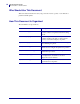
About This Document Who Should Use This Document Who Should Use This Document This User Guide is intended for use by any person who needs to operate or to troubleshoot problems with the printer. How This Document Is Organized The User Guide is set up as follows: 79695L-002 Rev. A Section Description Introduction on page 15 This section shows the operational controls and location of major components used when loading media.
About This Document Contacts Contacts You can contact Zebra Technologies Corporation at the following: Web Site http://www.zebra.com Technical Support via the Internet is available 24 hours per day, 365 days per year. Go to http://www.zebra.com/support. The Americas Regional Headquarters Technical Support Customer Service Dept. Zebra Technologies International, LLC 333 Corporate Woods Parkway Vernon Hills, Illinois 60061.3109 U.S.
About This Document Document Conventions Document Conventions The following conventions are used throughout this document to convey certain information. Alternate Color (online only) Cross-references contain hot links to other sections in this guide. If you are viewing this guide online in .pdf format, you can click the cross-reference (blue text) to jump directly to its location. LCD Display Examples Text from a printer’s Liquid Crystal Display (LCD) appears in Bubbledot ICG font.
About This Document Document Conventions Illustration Callouts Callouts are used when an illustration contains information that needs to be labeled and described. A table that contains the labels and descriptions follows the graphic. Figure 1 provides an example. Figure 1 • Sample Figure with Callouts 1 2 1 2 6/6/08 FEED button CANCEL button Z Series®/RZ™ Series User Guide 79695L-002 Rev.
About This Document Document Conventions Notes • ___________________________________________________________________ __________________________________________________________________________ __________________________________________________________________________ __________________________________________________________________________ __________________________________________________________________________ __________________________________________________________________________ ______________
1 Introduction This section shows the operational controls and location of major components used when loading media. Contents External View . . . . . . . . . . . . . . . . . . . . . . . . . . . . . . . . . . . . . . . . . . . . . . . . . . . . . . . . . . Printer Media Compartment . . . . . . . . . . . . . . . . . . . . . . . . . . . . . . . . . . . . . . . . . . . . . . . Control Panel . . . . . . . . . . . . . . . . . . . . . . . . . . . . . . . . . . . . . . . . . . . . . . . . . . . . . . . . . .
Introduction External View External View Figure 2 and Figure 3 show the components and connections on the outside of the printer. Figure 2 • Front of Printer 2 1 1 2 79695L-002 Rev.
Introduction External View Figure 3 • Rear of Printer (All Standard Connectors, Internal 10/100 Wired Print Server, and Wireless Plus Print Server Shown) 3 4 5 1 6 7 2 8 (All Standard Connectors, Internal 10/100 Wired Print Server, and Internal Wireless Plus Print Server Shown) 9 5 1 2 Power switch (O = off, I = on) AC power connector 5 6 3 Wireless card ejector button 4 Wireless Plus print server card slot (Ethernet option) 7 8 9 6/6/08 1 6 7 2 8 Serial port Internal wired print serve
Introduction Printer Media Compartment Printer Media Compartment Figure 4 shows the components inside the media compartment of your printer. Depending on installed options, your printer may look slightly different. Note • For optimal printing quality and proper printer performance across our product line, Zebra strongly recommends the use of genuine Zebra™ supplies as part of the total solution.
Introduction Control Panel Control Panel The control panel contains the lights that indicate basic operation and the buttons that you may need to press during basic operation. The control panel buttons and lights are labeled in Figure 5. Descriptions for each are located in Table 1 and Table 2.
Introduction Control Panel Control Panel Buttons Table 1 • Control Panel Buttons Button Function FEED Forces the printer to feed one blank label each time the button is pressed. • Printer not printing: one blank label immediately feeds. • Printing: one blank label feeds after the current batch of labels is complete. PAUSE Starts and stops the printing process. • Printer not printing: no printing occurs. (Press PAUSE again to resume printing.
Introduction Control Panel Control Panel Lights Table 2 • Control Panel Lights Light Status Indication POWER Off The printer is off, or no power is applied. On The printer is on. Off Normal printer operation. On The printer has stopped all printing operations. Flashing The Pause light flashes when initializing FLASH memory and in Peel-Off Mode when the label is available. Off Normal printer operation (no errors). PAUSE ERROR On An error condition is preventing printing.
Introduction Printer Language Modes Printer Language Modes Depending on how your printer was ordered, it came from the factory with firmware that operates in or allows you to use certain commands for one of the following printer languages: • Zebra Programming Language (ZPL®), which includes XML • Eltron® Programming Language (EPL™) • Datamax® Programming Language (APL-D™) • Intermec® Printer Language (APL-I™) Note • The following restrictions apply: • EPL, APL-D, and APL-I are supported only on 203 dp
2 Printer Setup This section provides the tasks that you must complete and the issues that you must consider before you load and configure your printer. Contents Before You Begin . . . . . . . . . . . . . . . . . . . . . . . . . . . . . . . . . . . . . . . . . . . . . . . . . . . . . . . Handling the Printer . . . . . . . . . . . . . . . . . . . . . . . . . . . . . . . . . . . . . . . . . . . . . . . . . . . . . Unpack and Inspect the Printer . . . . . . . . . . . . . . . . . . . . . . . . . . . . . . . .
Printer Setup Before You Begin Before You Begin Review this checklist, and resolve any issues before you set up or use your printer. Unpack and Inspect the Printer Have you unpacked the printer and inspected it for damage? If you have not, see Unpack and Inspect the Printer on page 25. Select a Site Have you selected an appropriate location for the printer? If you have not, see Select a Site for the Printer on page 26.
Printer Setup Handling the Printer Handling the Printer This section describes how to handle your printer. Unpack and Inspect the Printer When you receive the printer, immediately unpack it and inspect for shipping damage. • Save all packing materials. • Check all exterior surfaces for damage. • Raise the media door, and inspect the media compartment for damage to components. If you discover shipping damage upon inspection: • Immediately notify the shipping company and file a damage report.
Printer Setup Select a Site for the Printer Select a Site for the Printer Consider the following when selecting an appropriate location for your printer. Select a Surface Select a solid, level surface of sufficient size and strength to accommodate the printer and other equipment (such as a computer), if necessary. The choices include a table, countertop, desk, or cart. For the printer’s weight and dimensions, see General Specifications on page 142.
Printer Setup Select a Data Communication Interface Select a Data Communication Interface Table 5 provides basic information about data communication interfaces that you can use to connect your printer to a computer. You may send label formats to the printer through any data communication interface that is available. Select an interface that is supported by both your printer and your computer or your Local Area Network (LAN).
Printer Setup Select a Data Communication Interface Data Cables and Wireless Cards You must supply all data cables or wireless cards for your application. Data Cables Ethernet cables do not require shielding, but all other data cables must be fully shielded and fitted with metal or metallized connector shells. Unshielded data cables may increase radiated emissions above the regulated limits. To minimize electrical noise pickup in the cable: • Keep data cables as short as possible.
Printer Setup Select a Data Communication Interface Table 6 • Connecting the Printer to a Computer or Network 6/6/08 Interface Connection and Configuration RS-232 Serial The baud rate, number of data and stop bits, the parity, and the XON/XOFF or DTR control must match those of the host computer. See Standard Control Panel Parameters on page 69 to view or change these parameters. IEEE 1284 Bidirectional Parallel No additional configuration is necessary.
Printer Setup Select a Data Communication Interface Table 6 • Connecting the Printer to a Computer or Network (Continued) Interface Connection and Configuration USB No additional configuration is necessary. Caution • Be careful not to plug the USB cable into the wired Ethernet print server connector on the printer because doing so will damage the connector. 79695L-002 Rev.
Printer Setup Connect the Printer to a Power Source Connect the Printer to a Power Source The AC power cord must have a three-prong female connector on one end that plugs into the mating AC power connector at the rear of the printer. If a power cable was not included with your printer, refer to Power Cord Specifications on page 32. Caution • For personnel and equipment safety, always use an approved three-conductor power cord specific to the region or country intended for installation.
Printer Setup Connect the Printer to a Power Source Power Cord Specifications Caution • For personnel and equipment safety, always use an approved three-conductor power cord specific to the region or country intended for installation. This cord must use an IEC 320 female connector and the appropriate region-specific, three-conductor grounded plug configuration. Depending on how your printer was ordered, a power cord may or may not be included.
Printer Setup Types of Media Types of Media Important • Zebra strongly recommends the use of Zebra-brand supplies for continuous high-quality printing. A wide range of paper, polypropylene, polyester, and vinyl stock has been specifically engineered to enhance the printing capabilities of the printer and to prevent premature printhead wear. To purchase supplies, go to http://www.zebra.com/howtobuy.
Printer Setup Types of Media Table 7 • Roll and Fanfold Media Media Type Non-Continuous Roll Media How It Looks Description Roll media is wound on a 3-in. (76-mm) core. Individual labels are separated by one or more of the following methods: • Web media separates labels by gaps, holes, or notches. • Black mark media uses pre-printed black marks on the back side of the media to indicate label separations.
Printer Setup Ribbon Overview Ribbon Overview Ribbon is a thin film that is coated on one side with wax, resin, or wax resin, which is transferred to the media during the thermal transfer process. The media determines whether you need to use ribbon and how wide the ribbon must be. When ribbon is used, it must be as wide as or wider than the media being used. If the ribbon is narrower than the media, areas of the printhead are unprotected and subject to premature wear.
Printer Setup Ribbon Overview 4. Observe the results. Did flakes or particles of ink from the ribbon adhere to the label? If ink from the ribbon... Then... Adhered to the label The ribbon is coated on the outside and can be used with the standard Thermal Transfer option (black ribbon spindle). In the ribbon loading procedure, instructions are marked with this symbol.
3 Operations This section provides the procedures for loading and calibrating the printer. Note • Complete the tasks and resolve the issues in Printer Setup on page 23 before operating the printer. Contents Print Modes and Printer Options . . . . . . . . . . . . . . . . . . . . . . . . . . . . . . . . . . . . . . . . . . . Print Mode Descriptions and Printer Requirements . . . . . . . . . . . . . . . . . . . . . . . . . . . Media Paths . . . . . . . . . . . . . . . . . . . . . . . . . . . . . . . . . . .
Operations Print Modes and Printer Options Print Modes and Printer Options The printer can use different print modes and options for label removal (Table 8). Use a print mode that matches the media being used and the printer options available. For more information on the types of media, see Types of Media on page 33. To select a print mode, see Select Print Mode on page 72.
Operations Print Modes and Printer Options Media Paths Table 9 shows the media paths for print mode and printer option combinations using roll media. Fanfold media uses the same print modes and printer options as roll media. RFID printers can use all of these printer options and have the same media paths.
Operations Print Modes and Printer Options Table 9 • Media Paths for Print Modes with Various Printer Options (Continued) Media Path Print Mode Printer Option Cutter or Delayed Cut Cutter (shown with an optional catch tray) Rewind Rewind Red solid lines = media, Blue dotted lines = backing only 79695L-002 Rev.
Operations Load Media Load Media The beginning steps for loading media apply to all printers, including those that have the peel-off, liner take-up, cutter, or rewind option. When you have completed these beginning steps, continue with the media loading instructions for the print mode and printer options that apply to you. For more information about print modes and printer options, see Print Modes and Printer Options on page 38.
Operations Load Media 3. Insert media into the printer. Follow the instructions for roll or fanfold media, as appropriate. Fanfold Media Roll Media a. Remove and discard any tags or labels that are dirty or that are held by adhesives or tape. a. Flip down the media supply guide. b. Flip down the media supply guide. b. Feed the media through the rear or bottom access slot. Rear Feed c. Place the roll of media on the media supply hanger. Push the roll as far back as it will go.
Operations Load Media Fanfold Media (Continued) Roll Media (Continued) e. Slide in the media supply guide until it touches the edge of the roll. d. Flip up the media supply guide. e. Slide in the media supply guide until it touches the edge of the media. 4. Feed the media under the dancer assembly (1), the upper media sensor (2), and the ribbon sensor (3). Slide the media back until it touches the inside back wall of the upper media sensor. 3 2 1 5.
Operations Load Media Additional Steps for Tear-Off Mode After completing Beginning Steps for all Print Modes and Printer Options on page 41, continue with this section to operate the printer in Tear-Off mode. To operate the printer in Tear-Off mode, complete these steps: 1. Slide in the media guide until it touches the outer edge of the media. 2. Set the printer to Tear-Off mode. See Select Print Mode on page 72 for instructions. 3. Close the printhead assembly. 4.
Operations Load Media Additional Steps for Peel-Off Mode (with or without Liner Take-Up) After completing Beginning Steps for all Print Modes and Printer Options on page 41, continue with this section to operate the printer in Peel-Off mode with or without liner take-up. Your printer must have the Peel option, the Liner Take-Up option, or the Rewind option installed. See Print Modes and Printer Options on page 38 for more information.
Operations Load Media 3. Push down the peel-off mechanism release lever to open the peel assembly. 4. Feed the liner over the tear-off/peel-off bar (1) and behind the peel assembly (2). Make sure that the end of the liner falls outside of the printer. 1 2 5. Complete this step only if you want to use Peel-Off mode with liner take-up. Your printer must have the Liner Take-Up option or the Rewind option installed. Follow the instructions for your printer option. Rewind Option a.
Operations Load Media Rewind Option (Continued) 6/6/08 b. Loosen the thumbscrew on the rewind media guide. c. Slide the rewind media guide all the way out, and then fold it down. d. Slide an empty core onto the rewind spindle. Liner Take-Up Option (Continued) b. Push the liner back until it touches the back plate of the liner take-up spindle assembly. c. Wrap the liner around the liner take-up spindle and turn the spindle counterclockwise to tighten the liner.
Operations Load Media Rewind Option (Continued) 79695L-002 Rev. A e. Wrap the liner around the core and turn the rewind spindle counterclockwise to tighten the liner. f. Fold up the rewind media guide, and then slide it in until it touches the liner. g. Tighten the thumbscrew on the rewind media guide. Liner Take-Up Option (Continued) (No additional steps for the liner take-up option.
Operations Load Media 6. Caution • Use the peel release lever and your right hand to close the peel assembly. Do not use your left hand to assist in closing. The top edge of the peel roller/assembly could pinch your fingers. Close the peel assembly using the peel-off mechanism release lever. 7. Slide in the media guide until it touches the outer edge of the media. 8. Set the printer to Peel-Off mode. See Select Print Mode on page 72 for instructions. 9. Close the printhead assembly. 10.
Operations Load Media Additional Steps for Cutter or Delayed Cut Mode After completing Beginning Steps for all Print Modes and Printer Options on page 41, continue with this section to operate the printer in Cutter or Delayed Cut mode. To operate the printer in Cutter or Delayed Cut mode, complete these steps: 1. Caution • The cutter blade is sharp. Do not touch or rub the blade with your fingers. Feed the media through the cutter (1). 1 2.
Operations Load Media 4. Close the printhead assembly. 5. If the printer is paused (the Pause light is on), press PAUSE to enable printing. Cutting begins automatically. Additional Steps for Rewind Mode After completing Beginning Steps for all Print Modes and Printer Options on page 41, continue with this section to operate the printer in Rewind mode. For additional procedures related to the rewind option, see Routine Maintenance for the Rewind Option on page 110.
Operations Load Media 2. Feed the media over the peel assembly (1). 1 3. Feed the media under the media alignment roller (1). 1 4. Loosen the thumbscrew on the rewind media guide. 5. Slide the rewind media guide all the way out, and then fold it down. 79695L-002 Rev.
Operations Load Media 6. Slide an empty core onto the rewind spindle. 7. Wrap the media around the core and turn the rewind spindle counterclockwise to tighten the media. Ensure that the edge of the media is flush against the backplate of the rewind spindle. 8. Fold up the rewind media guide, and then slide it in until it touches the media. 9. Tighten the thumbscrew on the rewind media guide. 6/6/08 Z Series®/RZ™ Series User Guide 79695L-002 Rev.
Operations Load Media 10. Slide in the media guide until it touches the outer edge of the media. 11. Set the printer to Rewind mode. See Select Print Mode on page 72 for instructions. 12. Close the printhead assembly. 13. If the printer is paused (the Pause light is on), press PAUSE to enable printing. Rewinding begins automatically. 79695L-002 Rev.
Operations Load Ribbon Load Ribbon Always use ribbon that is wider than the media to protect the printhead from wear. For direct thermal printing, do not load ribbon in the printer. The standard Thermal Transfer option (black ribbon spindle) uses ribbon coated on the outside, and the alternate Thermal Transfer option (gray ribbon spindle) uses ribbon coated on the inside. To avoid damaging your printer, follow the directions for the Thermal Transfer option installed in your printer.
Operations Load Ribbon Caution • While performing any tasks near an open printhead, remove all rings, watches, hanging necklaces, identification badges, or other metallic objects that could touch the printhead. You are not required to turn off the printer power when working near an open printhead, but Zebra recommends it as a precaution. If you turn off the power, you will lose all temporary settings, such as label formats, and you must reload them before you resume printing.
Operations Load Ribbon 3. Insert the ribbon into the printer. In this step, follow the instructions for the Thermal Transfer option installed in your printer. Ribbon Coated Outside (black ribbon spindle) Ribbon Coated Inside (gray ribbon spindle) a. Hold the ribbon with the loose end unrolling clockwise. a. Hold the ribbon with the loose end unrolling counterclockwise. b. Place the roll of ribbon on the ribbon supply spindle (1) and push it all the way back. b.
Operations Load Ribbon 4. Close the printhead assembly. 5. Wind the ribbon clockwise onto the ribbon take-up spindle (1). Ribbon Coated Outside (black ribbon spindle) Ribbon Coated Inside (gray ribbon spindle) 1 79695L-002 Rev.
Operations Load Ribbon Remove Used Ribbon To remove used ribbon, complete these steps: 1. Caution • Do not cut the ribbon directly on the ribbon take-up spindle. Doing so may damage the spindle. If the ribbon has not run out, cut or break it before the ribbon take-up spindle (1). 1 2. To loosen the ribbon, squeeze it against the ribbon take-up spindle tension blades (1). At the same time, turn the ribbon take-up spindle release knob counterclockwise (2).
Operations Calibrate the Printer Calibrate the Printer The printer can be set to calibrate automatically, or you can calibrate it manually. Auto Calibration When the control panel setting for MEDIA POWER UP or HEAD CLOSE is set to CALIBRATION, the printer automatically calibrates on power up or when the printhead is closed. During auto calibration, the printer determines the label length and sensor settings.
Operations Adjust Printhead Pressure Adjust Printhead Pressure You may need to adjust printhead pressure if printing is too light on one side, if you use thick media, or if the media drifts from side to side during printing. See Figure 10. The ZM400 and RZ400 pressure adjustment dials have four possible settings designated by blocks of increasing size embossed on the print mechanism.
Operations Adjust Printhead Pressure Table 11 • ZM600 and RZ600 Printhead Pressure Media Width Inside Dial Outside Dial 2 in. (50 mm) 6 1 3 in. (75 mm) 6 2 4 in. (100 mm) 7 3 5 in. (125 mm) 7 4 5.5 in. and up (140 mm and up) 6 6 2. If necessary, adjust the pressure adjustment dials as follows: 79695L-002 Rev. A If the media... Then... Requires higher pressure to print well Increase both dials one position.
4 Configuration This section describes the control panel parameters that are used to configure the printer for operation. Contents Setup Mode . . . . . . . . . . . . . . . . . . . . . . . . . . . . . . . . . . . . . . . . . . . . . . . . . . . . . . . . . . . Enter and Use Setup Mode . . . . . . . . . . . . . . . . . . . . . . . . . . . . . . . . . . . . . . . . . . . . . Exit Setup Mode. . . . . . . . . . . . . . . . . . . . . . . . . . . . . . . . . . . . . . . . . . . . . . . . . . . . . .
Configuration Setup Mode Setup Mode After you have installed the media and ribbon and the Power-On Self Test (POST) is complete, the control panel displays PRINTER READY. You may now set printer parameters for your application using the control panel display and the buttons directly below it. If it becomes necessary to restore the initial printer defaults, see FEED and PAUSE Self Test on page 137.
Configuration Setup Mode Exit Setup Mode When you exit setup mode, you have several options for saving, changing, or not changing parameters. To leave Setup mode, complete these steps: 1. Press SETUP/EXIT. The LCD displays SAVE CHANGES. 2. Press PLUS (+) or MINUS (-) to display the save options: LCD Description PERMANENT Stores values in the printer even when power is turned off. TEMPORARY Saves the changes until power is turned off.
Configuration Change Password-Protected Parameters Change Password-Protected Parameters Certain parameters, including the communication parameters, are password-protected by factory default. Caution • Do not change password-protected parameters unless you have a complete understanding of the parameters’ functions. If the parameters are set incorrectly, the printer may function unpredictably. The first time that you attempt to change a password-protected parameter, the printer displays ENTER PASSWORD.
Configuration Print a Configuration Label Print a Configuration Label A configuration label lists the printer settings that are stored in configuration memory. After you load the media, print a configuration label as a record of your printer’s current settings. Keep the label to use when troubleshooting printing problems. To print a configuration label, complete these steps: 1. On the control panel, press SETUP/EXIT. 2.
Configuration Print a Network Configuration Label Print a Network Configuration Label If you are using a print server, you can print a network configuration label after the printer is connected to the network. To print a network configuration label, complete these steps: 1. On the control panel, press SETUP/EXIT. 2. Press PLUS (+) or MINUS (-) to scroll through the parameters until you reach LIST NETWORK. 3. Press SELECT to select the parameter. 4. Press PLUS (+) to confirm printing.
Configuration Standard Control Panel Parameters Standard Control Panel Parameters Table 12 shows parameters in the order in which they are displayed when you press PLUS (+) after entering Setup mode. For parameters that do not appear in this table, see Additional Control Panel Parameters on page 95. Note • Your label preparation software or the printer driver may override adjustments made through the control panel. Refer to the software or driver documentation for more information.
Configuration Standard Control Panel Parameters Table 12 • Printer Parameters (Page 2 of 26) Language/Parameter Action/Explanation Adjust Print Speed Adjusts the speed for printing a label (given in inches per second). Slower print speeds typically yield better print quality. Print speed changes take effect upon exiting Setup mode.
Configuration Standard Control Panel Parameters Table 12 • Printer Parameters (Page 3 of 26) Language/Parameter Action/Explanation Adjust the Tear-Off Position This parameter establishes the position of the media over the tear-off/peel-off bar after printing. See Figure 13. Higher numbers move the media out (the tear line moves closer to the leading edge of the next label), and lower numbers move the media in (the tear line moves closer to the edge of the label just printed).
Configuration Standard Control Panel Parameters Table 12 • Printer Parameters (Page 4 of 26) Language/Parameter Action/Explanation Select Print Mode This parameter tells the printer how printed labels will be removed. Make sure that you select a print mode that is compatible with your printer and printer options. For information about how the print modes work with different printer options, see Print Modes and Printer Options on page 38.
Configuration Standard Control Panel Parameters Table 12 • Printer Parameters (Page 5 of 26) Language/Parameter APL-D only Action/Explanation Set Module A Storage Device for APL-D Default Value: NONE Selections: NONE, RAM 1, RAM 2, FLASH 1, FLASH 2 To change the value shown: Press SELECT to select the parameter. 2. Press PLUS (+) or MINUS (-) to scroll through the options. 3. Press SELECT to accept any changes and deselect the parameter. 1.
Configuration Standard Control Panel Parameters Table 12 • Printer Parameters (Page 6 of 26) Language/Parameter Action/Explanation Select Print Method The print method parameter tells the printer the method of printing that you want to use: direct thermal (no ribbon) or thermal transfer (using thermal transfer media and ribbon). Default Value: THERMAL TRANSFER Selections: THERMAL TRANSFER, DIRECT THERMAL To change the value shown: Press SELECT to select the parameter. 2.
Configuration Standard Control Panel Parameters Table 12 • Printer Parameters (Page 7 of 26) Language/Parameter ZPL, EPL, APL-I APL-D only Action/Explanation Set Maximum Label Length This parameter is used during the media portion of the calibration process. Always set maximum label length to a value that is at least 1.0 in. (25.4 mm) greater than the actual label length (Figure 14).
Configuration Standard Control Panel Parameters Table 12 • Printer Parameters (Page 8 of 26) Language/Parameter Action/Explanation Set Early Warning for Maintenance When this feature is enabled, the printer provides warnings when the printhead needs to be cleaned. Default Value: MAINT. OFF Selections: MAINT. OFF, MAINTENANCE ON To change the Early Warning settings: Press SELECT to select the parameter.
Configuration Standard Control Panel Parameters Table 12 • Printer Parameters (Page 9 of 26) Language/Parameter Action/Explanation Set Printhead Life for Early Warning This parameter appears only when Early Warning for Maintenance is enabled. Set this value to the number of inches of media that the printhead is expected to print. Default Value: 1,000,000 inches Range: 100 to 1,000,000 inches To change the value shown: Press SELECT to select the parameter. 2. Press MINUS (-) to move the cursor. 3.
Configuration Standard Control Panel Parameters Table 12 • Printer Parameters (Page 10 of 26) Language/Parameter Action/Explanation Print Counter Readings Prints a label that lists the odometer readings for the following: • the non-resettable counter • the two user-controlled counters • the Early Warning for Maintenance counters, which indicate when the printhead was last cleaned and the printhead life If the Early Warning for Maintenance feature is disabled, the counters related to it do not print.
Configuration Standard Control Panel Parameters Table 12 • Printer Parameters (Page 11 of 26) Language/Parameter ZPL, EPL, APL-D Action/Explanation List Formats This option prints a label that lists the available formats stored in the printer’s RAM, Flash memory, or optional memory card. To print a list of the available formats: Press SELECT to select the parameter. 2. Press PLUS (+) to select PRINT. 3. Press SELECT to deselect the parameter. 1.
Configuration Standard Control Panel Parameters Table 12 • Printer Parameters (Page 12 of 26) Language/Parameter APL-I only Action/Explanation Print Quality Test Label A print quality test label contains test bar codes and relevant printer settings. To print this label: Press SELECT to select the parameter. 2. Press PLUS (+) to select PRINT. 3. Press SELECT to deselect the parameter. 1. APL-I only Print Pitch Test Label To print this label: Press SELECT to select the parameter. 2.
Configuration Standard Control Panel Parameters Table 12 • Printer Parameters (Page 13 of 26) Language/Parameter APL-I only Action/Explanation Print Stored APL-I Format Up to 100 formats can be stored and printed. Selections: 0 through 99 Default Value: 0 To modify this parameter: To print this label: Press SELECT to select the parameter. 2. Press PLUS (+) to select PRINT. 3. Press SELECT to deselect the parameter. 1.
Configuration Standard Control Panel Parameters Table 12 • Printer Parameters (Page 14 of 26) Language/Parameter Action/Explanation Initialize Flash Memory This option erases all previously stored information from Flash memory. Caution • This option completely erases the Flash memory. To initialize Flash memory: Press SELECT to select the parameter. 2. If prompted for a password, enter the printer password. For instructions, see Change Password-Protected Parameters on page 66. 1.
Configuration Standard Control Panel Parameters Table 12 • Printer Parameters (Page 15 of 26) Language/Parameter Action/Explanation Calibrate Media and Ribbon Sensor Sensitivity Use this procedure to adjust sensitivity of media and ribbon sensors. Important • Follow this procedure exactly as presented. All of the steps must be performed even if only one of the sensors requires adjustment. You may press MINUS (-) at any step in this procedure to cancel the process.
Configuration Standard Control Panel Parameters Table 12 • Printer Parameters (Page 16 of 26) Language/Parameter Action/Explanation Set Parallel Communications Select the communications port that matches the one being used by the host computer. Default Value: BIDIRECTIONAL Selections: BIDIRECTIONAL, UNIDIRECTIONAL To change the value shown: Press SELECT to select the parameter. 2. Press PLUS (+) or MINUS (-) to scroll through the options. 3.
Configuration Standard Control Panel Parameters Table 12 • Printer Parameters (Page 17 of 26) Language/Parameter Action/Explanation Set Data Bits This setting applies only when the serial port is used. The data bits of the printer must match the data bits of the host computer for accurate communications to take place. Set the data bits to match the setting being used by the host computer. Default Value: 8 BITS Selections: 7 BITS, 8 BITS To change the value shown: Press SELECT to select the parameter. 2.
Configuration Standard Control Panel Parameters Table 12 • Printer Parameters (Page 18 of 26) Language/Parameter APL-I only Action/Explanation Send APL-I Status Response Determines if a response is sent after inquiry commands. Default Value: ON Selections: ON, OFF To change the value shown: Press SELECT to select the parameter. 2. Press PLUS (+) or MINUS (-) to toggle between the options. 3. Press SELECT to accept any changes and deselect the parameter. 1.
Configuration Standard Control Panel Parameters Table 12 • Printer Parameters (Page 19 of 26) Language/Parameter Action/Explanation Set Communications Mode The communication diagnostics mode is a troubleshooting tool for checking the interconnection between the printer and the host computer. For more information, see Communications Diagnostics Test on page 138. Default Value: NORMAL MODE Selections: NORMAL MODE, DIAGNOSTICS To select communication diagnostics mode: Press SELECT to select the parameter.
Configuration Standard Control Panel Parameters Table 12 • Printer Parameters (Page 20 of 26) Language/Parameter ZPL only Action/Explanation Set Delimiter Character The delimiter character is a two-digit hex value used as a parameter place marker in ZPL/ZPL II format instructions. See the ZPL Programming Guide for more information. Note • Do not use the same hex value for the control, format, and delimiter character. The printer must see different characters to work properly.
Configuration Standard Control Panel Parameters Table 12 • Printer Parameters (Page 21 of 26) Language/Parameter Action/Explanation Select Media Power-Up Option This parameter sets the action of the media when you turn on the printer. Default Value (non-RFID printers): CALIBRATION Default Value (RFID printers): FEED Selections: CALIBRATION, SHORT CAL, LENGTH, NO MOTION, FEED • Calibration adjusts sensor levels and thresholds, determines length, and feeds the media to the next web.
Configuration Standard Control Panel Parameters Table 12 • Printer Parameters (Page 22 of 26) Language/Parameter Action/Explanation Select Backfeed Sequence This parameter sets when label backfeed occurs after a label is removed in some print modes. It has no effect in Rewind mode. This setting is superseded by ~JS when received as part of a label format (see the ZPL Programming Guide for more information).
Configuration Standard Control Panel Parameters Table 12 • Printer Parameters (Page 23 of 26) Language/Parameter Action/Explanation Adjust Left Position This parameter adjusts the print position horizontally on the label. Positive numbers adjust printing to the left by the specified number of dots. Negative numbers shift printing to the right. Default Value: 0000 Range: –9999 to +9999 dots To change the value shown: Press SELECT to select the parameter. 2. Press MINUS (-) to move the cursor. 3.
Configuration Standard Control Panel Parameters Table 12 • Printer Parameters (Page 24 of 26) Language/Parameter See next column Action/Explanation View Sensor Settings These parameters are automatically set during the calibration procedure and should be changed only by a qualified service technician. Refer to the ZPL II Programming Guide for information on these parameters. To skip these parameters: 1.
Configuration Standard Control Panel Parameters Table 12 • Printer Parameters (Page 25 of 26) Language/Parameter Action/Explanation Select Idle Display This parameter selects the LCD options for the real-time clock. Note • If the default value is not selected, pressing PLUS (+) or MINUS (-) briefly displays the firmware version of the printer.
Configuration Standard Control Panel Parameters Table 12 • Printer Parameters (Page 26 of 26) Language/Parameter Action/Explanation Select the Display Language This parameter changes the language displayed on the LCD. Each language selection is displayed in the language itself.
Configuration Additional Control Panel Parameters Additional Control Panel Parameters Additional parameters appear in the following situations. • When a Radio Frequency Identification (RFID) reader is installed. These parameters are shown in Table 14 on page 96. • When a wired print server is installed in the printer. For more information, refer to the ZebraNet 10/100 Print Server User and Reference Guide • When a wireless print server is installed in the printer. Refer to the ZebraNet Wireless User Guide.
RFID Operation Additional Control Panel Parameters RFID Control Panel Parameters The parameters shown in Table 14 display only if the printer has an RFID reader installed. Table 14 • RFID Parameters (Page 1 of 4) Parameter RFID TEST QUICK Action/Explanation SLOW Perform RFID Test In the RFID test, the printer attempts to read and write to a transponder. In the slow version, the printer first displays the hardware version, the reader firmware version, and the program position.
RFID Operation Additional Control Panel Parameters Table 14 • RFID Parameters (Page 2 of 4) Parameter Action/Explanation Calibrate RFID Tag RFID TAG CALIB RESTORE RUN RESTORE Selecting this option resets the RFID programming position to the label length minus 1 mm (0.04 in.). RUN If the media being used does not conform to transponder placement requirements for your printer, use the RUN option to have the printer determine the optimum programming position for the non-standard labels.
RFID Operation Additional Control Panel Parameters Table 14 • RFID Parameters (Page 3 of 4) Parameter RFID WRITE PWR 16 Action/Explanation View or Change RFID Write Power This parameter displays the current value for RFID write power. Default: 16 Selections: 0 to 30 To change the value shown: Press SELECT to select the parameter. 2. Press PLUS (+) or MINUS (-) to scroll through the options. 3. Press SELECT to accept any changes and deselect the parameter. 1.
RFID Operation Additional Control Panel Parameters Table 14 • RFID Parameters (Page 4 of 4) Parameter RFID TAG DATA Action/Explanation Read and Display RFID Tag Data When this option is selected, the reader attempts to read a tag over the RFID antenna, even if the printhead is open. Results are displayed in hexadecimal format. The printer rereads the tag every 2 seconds, so if the tag changes, data is displayed for the current tag over the antenna.
RFID Operation Additional Control Panel Parameters Notes • ___________________________________________________________________ __________________________________________________________________________ __________________________________________________________________________ __________________________________________________________________________ __________________________________________________________________________ __________________________________________________________________________ ___
5 Routine Maintenance This section provides routine cleaning and maintenance procedures. Contents Replacing Printer Components . . . . . . . . . . . . . . . . . . . . . . . . . . . . . . . . . . . . . . . . . . . Ordering Replacement Parts . . . . . . . . . . . . . . . . . . . . . . . . . . . . . . . . . . . . . . . . . . . Recycling Printer Components . . . . . . . . . . . . . . . . . . . . . . . . . . . . . . . . . . . . . . . . . Lubrication . . . . . . . . . . . . . . . . . . . . . . . . . . . . . . .
Routine Maintenance Replacing Printer Components Replacing Printer Components Some printer components, such as the printhead and platen roller, may wear out over time and can be replaced easily. Regular cleaning may extend the life of some of these components. See Cleaning Schedule and Procedures on page 103 for the recommended cleaning intervals.
Routine Maintenance Cleaning Schedule and Procedures Cleaning Schedule and Procedures Important • Zebra is not responsible for damage caused by the use of cleaning fluids on this printer. Specific cleaning procedures are provided on the following pages. Table 15 shows the recommended cleaning schedule. These intervals are intended as guidelines only. You may have to clean more often, depending upon your application and media. .
Routine Maintenance Cleaning Procedures Clean the Printhead and Platen Roller You can minimize printhead wear and maintain print quality with regular preventive measures. Over time, the movement of media or ribbon across the printhead wears through the protective ceramic coating, exposing and eventually damaging the print elements (dots). To avoid abrasion: • Clean the printhead frequently, and use well-lubricated thermal transfer ribbons with backings optimized to reduce friction.
Routine Maintenance Cleaning Procedures Caution • The printhead may be hot and could cause severe burns. Allow the printhead to cool. Caution • Before touching the printhead assembly, discharge any built-up static electricity by touching the metal printer frame or by using an antistatic wriststrap and mat. To clean the printhead and platen roller, complete these steps: 1. Open the printhead assembly. 2. Remove the media and ribbon. 3.
Routine Maintenance Cleaning Procedures 4. While manually rotating the platen roller, clean it thoroughly with the swab. Allow the solvent to evaporate. 5. Reload media and ribbon, and close the printhead assembly. Note • If performing this procedure does not improve print quality, try cleaning the printhead with Save-A-Printhead cleaning film. This specially coated material removes contamination buildup without damaging the printhead. Call your authorized Zebra reseller for more information.
Routine Maintenance Cleaning Procedures Clean the Media Compartment and Sensors To clean the media compartment and sensors, complete these steps: 1. Brush or vacuum any accumulated paper lint and dust away from the media and ribbon paths. 2. Brush or vacuum any paper lint and dust away from the sensors (see Figure 17). Figure 17 • Cleaning the Sensors 1 3 2 1 2 3 6/6/08 Take-label sensor Ribbon sensor Media sensor Z Series®/RZ™ Series User Guide 79695L-002 Rev.
Routine Maintenance Cleaning Procedures Clean the Cutter Module If the cutter is not cutting the labels cleanly or if it jams with labels, clean the cutter. Caution • For personnel safety, always power off and unplug the printer before performing this procedure. To clean the cutter module, complete these steps: 1. Turn the printer off (O), and unplug the printer from its power source. 2. Caution • The cutter blade is sharp. Do not touch or rub the blade with your fingers.
Routine Maintenance Cleaning Procedures 4. See Figure 18. Using the swab from the Preventive Maintenance Kit (part number 47362), wipe along the upper cutting surface (1) and the cutter blade (2). In place of the Preventive Maintenance Kit, you may use a clean swab dipped in a solution of isopropyl alcohol (minimum 90%) and deionized water (maximum 10%). Allow the solvent to evaporate. Figure 18 • Cleaning the Cutter Module 1 2 5. Replace the cutter shield. 6.
Routine Maintenance Routine Maintenance for the Rewind Option Routine Maintenance for the Rewind Option When you use the Rewind option, you will periodically need to remove printed labels or used liner from the rewind spindle. You may also need to adjust the media alignment for the Rewind option. Remove Printed Labels or Liner from the Rewind Spindle To remove printed labels or liner from the rewind spindle, complete these steps: 1.
Routine Maintenance Routine Maintenance for the Rewind Option 4. Slide the rewind media guide all the way out, and then fold it down. 5. Slide the core with the liner from the take-up spindle. 6/6/08 Z Series®/RZ™ Series User Guide 79695L-002 Rev.
Routine Maintenance Routine Maintenance for the Rewind Option Adjust Media Alignment for Rewind Option The instructions below apply only if the printer has a Rewind option. The liner should be installed flush against the backplate of the rewind spindle to prevent the media/backing from winding too loosely. Perform the adjustments in the order given. Do only what is needed to solve the problem. To adjust the media alignment for printers with the Rewind option, complete these steps: 1.
6 Troubleshooting This section provides information about errors that you might need to troubleshoot. Assorted diagnostic tests are included. Contents Troubleshooting Checklists . . . . . . . . . . . . . . . . . . . . . . . . . . . . . . . . . . . . . . . . . . . . . . LCD Error Messages . . . . . . . . . . . . . . . . . . . . . . . . . . . . . . . . . . . . . . . . . . . . . . . . . . . Print Quality Problems . . . . . . . . . . . . . . . . . . . . . . . . . . . . . . . . . . . . . . . . . . . . . . . .
Troubleshooting Troubleshooting Checklists Troubleshooting Checklists If an error condition exists with the printer, review this checklist: Are noncontinuous labels being treated as continuous labels? If yes, see Calibrate Media and Ribbon Sensor Sensitivity on page 83. Is the printer reporting a ribbon error when ribbon is loaded properly? If yes, see Calibrate Media and Ribbon Sensor Sensitivity on page 83.
Troubleshooting LCD Error Messages LCD Error Messages The LCD displays messages when there is an error. See Table 16 for LCD errors, the possible causes, and the recommended solutions. Table 16 • LCD Error Messages LCD Display/ Printer Condition ERROR CONDITION INVALID HEAD Possible Cause Recommended Solution The printhead was replaced with one that is not a genuine Zebra™ printhead. Install a genuine Zebra™ printhead. In thermal transfer mode, ribbon is not loaded or incorrectly loaded.
Troubleshooting LCD Error Messages Table 16 • LCD Error Messages (Continued) LCD Display/ Printer Condition WARNING RIBBON IN Possible Cause Recommended Solution Ribbon is loaded, but the printer is set for direct thermal mode. Ribbon is not required with direct thermal media. If you are using direct thermal media, remove the ribbon. This error message will not affect printing. The ERROR light flashes. ERROR CONDITION PAPER OUT The printer stops; the ERROR light flashes.
Troubleshooting LCD Error Messages Table 16 • LCD Error Messages (Continued) LCD Display/ Printer Condition WARNING HEAD COLD The printer prints while the ERROR light flashes. Possible Cause Recommended Solution Caution • An improperly connected printhead data or power cable can cause this error message. The printhead may be hot enough to cause severe burns. Allow the printhead to cool. The printhead temperature is approaching its lower operating limit.
Troubleshooting LCD Error Messages Table 16 • LCD Error Messages (Continued) LCD Display/ Printer Condition DEFRAGMENTING Possible Cause The printer is defragmenting memory. The printer stops. ERROR CONDITION CUTTER JAM The printer stops; the ERROR light flashes. OUT OF MEMORY (function) Recommended Solution Caution • Do NOT turn off the printer power during defragmenting. Doing so can damage the printer. Allow the printer to finish defragmenting.
Troubleshooting Print Quality Problems Print Quality Problems Table 17 identifies problems with print quality, the possible causes, and the recommended solutions. Table 17 • Print Quality Problems Problem Possible Cause Recommended Solution General print quality issues The printer is set at the incorrect print speed. For optimal print quality, set the print speed to the lowest possible setting for your application via control panel, the driver, or the software. See Adjust Print Speed on page 70.
Troubleshooting Print Quality Problems Table 17 • Print Quality Problems (Continued) Problem Possible Cause Recommended Solution Wrinkled ribbon Ribbon was fed through the ribbon system incorrectly. Load the ribbon correctly. See Load Ribbon on page 55. Incorrect burn temperature. Set the darkness to the lowest possible setting for good print quality. See Adjust Print Darkness/Density on page 69. Incorrect or uneven printhead pressure.
Troubleshooting Print Quality Problems Table 17 • Print Quality Problems (Continued) Problem Possible Cause Vertical drift in top-of-form position The printer is out of calibration. Recalibrate the printer. Vertical image or label drift The bar code printed on a label does not scan. 6/6/08 Recommended Solution Vertical drift occurs during normal printer operation. Note • A vertical drift of ± 4 to 6 dot rows (approximately 0.5 mm) is within normal tolerances. Calibrate the printer.
Troubleshooting Calibration Problems Calibration Problems Table 18 identifies problems with calibration, the possible causes, and the recommended solutions. Table 18 • Calibration Problems Problem Possible Cause Recommended Solution Loss of printing registration on labels. Excessive vertical drift in top-of-form registration. The platen roller is dirty. Clean the platen roller according to the instructions in Clean the Printhead and Platen Roller on page 104.
Troubleshooting Communications Problems Communications Problems Table 19 identifies problems with communications, the possible causes, and the recommended solutions. Table 19 • Communications Problems Problem Possible Cause Recommended Solution A label format was sent to the printer but was not recognized. The DATA light does not flash. The communication parameters are incorrect. Check the printer driver or software communications settings (if applicable).
Troubleshooting Ribbon Problems Ribbon Problems Table 20 identifies problems that may occur with ribbon, the possible causes, and the recommended solutions. Table 20 • Ribbon Problems Problem Possible Cause Recommended Solution Broken or melted ribbon Darkness setting too high. 1. Reduce the darkness setting. 2. Clean the printhead thoroughly. The printer does not detect when the ribbon runs out. The printer was calibrated without ribbon.
Troubleshooting RFID Problems RFID Problems Table 21 identifies problems that may occur with RFID printers, the possible causes, and the recommended solutions. For more information about RFID, refer to the RFID Programming Guide. A copy of the manual is available at http://www.zebra.com/manuals or on the user CD that came with your printer. Table 21 • RFID Problems Problem Possible Cause Recommended Solution The RFID-enabled printer voids every label.
Troubleshooting RFID Problems Table 21 • RFID Problems (Continued) Problem Possible Cause Recommended Solution Poor yields. Too many RFID tags per roll are voided. The RFID labels are not within specifications for the printer, which means that the transponder is not in an area that can be programmed consistently. Make sure that the labels meet transponder placement specifications for your printer. See http://www.zebra.
Troubleshooting RFID Problems Table 21 • RFID Problems (Continued) Problem Possible Cause Recommended Solution The DATA light flashes indefinitely after you attempt to download printer or reader firmware. The download was not successful. For best results, cycle power on the printer before downloading any firmware. 1. 2. 3. 4. 5. RFID parameters do not appear in Setup mode, and RFID information does not appear on the printer configuration label.
Troubleshooting Miscellaneous Printer Problems Miscellaneous Printer Problems Table 22 identifies miscellaneous problems with the printer, the possible causes, and the recommended solutions. Table 22 • Miscellaneous Printer Problems Problem Possible Cause Recommended Solution The LCD displays a language that I cannot read The language parameter was changed through the control panel or a firmware command. 1. Press SETUP/EXIT to enter configuration mode. 2. Press MINUS (-).
Troubleshooting Miscellaneous Printer Problems Table 22 • Miscellaneous Printer Problems (Continued) Problem Possible Cause Recommended Solution Changes in parameter settings did not take effect Parameters are set incorrectly. 1. Set parameters and save permanently. 2. Turn the printer off (O) and then on (I). A command turned off the ability to change the parameter. Refer to the ZPL Programming Guide, or call a service technician. A command changed the parameter back to the previous setting.
Troubleshooting Miscellaneous Printer Problems Table 22 • Miscellaneous Printer Problems (Continued) Problem Possible Cause Recommended Solution The printer locks up while running the Power-On Self Test. Main logic board failure. Call a service technician. The printer prints VOID on every label that I try to print. The printer is set for RFID operation, but you are not using RFID labels. Switch to RFID labels, or remove the RFID commands from your label formats. 79695L-002 Rev.
Troubleshooting Printer Diagnostics Printer Diagnostics Self tests and other diagnostics provide specific information about the condition of the printer. The self tests produce sample printouts and provide specific information that helps determine the operating conditions for the printer. The most commonly used are the Power-On and the CANCEL self tests. Important • Use full-width media when performing self tests. If your media is not wide enough, the test labels may print on the platen roller.
Troubleshooting Printer Diagnostics CANCEL Self Test The CANCEL self test prints a configuration label (Figure 19). To perform the CANCEL Self Test, complete these steps: 1. Turn off (O) the printer. 2. Press and hold CANCEL while turning on (I) the printer. Hold CANCEL until the first control panel light turns off. A printer configuration label prints (Figure 19). Figure 19 • Sample Configuration Label Z Series 79695L-002 Rev.
Troubleshooting Printer Diagnostics PAUSE Self Test This self test can be used to provide the test labels required when making adjustments to the printer’s mechanical assemblies or to determine if any printhead elements are not working. Figure 20 shows a sample printout. To perform a PAUSE self test, complete these steps: 1. Turn off (O) the printer. 2. Press and hold PAUSE while turning on (I) the printer. Hold PAUSE until the first control panel light turns off.
Troubleshooting Printer Diagnostics FEED Self Test Different types of media may require different darkness settings. This section contains a simple but effective method for determining the ideal darkness for printing bar codes that are within specifications. During the FEED self test, labels are printed at different darkness settings at two different print speeds. The relative darkness and the print speed are printed on each label.
Troubleshooting Printer Diagnostics 4. See Figure 22 and Table 23. Inspect the test labels and determine which one has the best print quality for your application. If you have a bar code verifier, use it to measure bars/spaces and calculate the print contrast. If you do not have a bar code verifier, use your eyes or the system scanner to choose the optimal darkness setting based on the labels printed in this self test.
Troubleshooting Printer Diagnostics Table 23 • Judging Bar Code Quality Print Quality Description Too dark Labels that are too dark are fairly obvious. They may be readable but not “in-spec.” • The normal bar code bars increase in size. • The openings in small alphanumeric characters may fill in with ink. • Rotated bar code bars and spaces run together. Slightly dark Slightly dark labels are not as obvious. • The normal bar code will be “in-spec.
Troubleshooting Printer Diagnostics FEED and PAUSE Self Test Performing this self test temporarily resets the printer configuration to the factory default values. These values are active only until power is turned off unless you save them permanently in memory. If the factory default values are permanently saved, a media calibration procedure must be performed. To perform a FEED and PAUSE self test, complete these steps: 1. Turn off (O) the printer. 2.
Troubleshooting Printer Diagnostics Communications Diagnostics Test The communication diagnostics test is a troubleshooting tool for checking the interconnection between the printer and the host computer. When the printer is in diagnostics mode, it prints all data received from the host computer as straight ASCII characters with the hex values below the ASCII text. The printer prints all characters received, including control codes such as CR (carriage return).
Troubleshooting Printer Diagnostics Sensor Profile Use the sensor profile label to troubleshoot the following types of problems: • If the media sensor experiences difficulty in determining gaps (web) between labels. • If the media sensor incorrectly identifies preprinted areas on a label as gaps (web). • If the ribbon sensor cannot detect ribbon. For instructions on printing a sensor profile, see Print Sensor Profile on page 82.
Troubleshooting Printer Diagnostics Notes • ___________________________________________________________________ __________________________________________________________________________ __________________________________________________________________________ __________________________________________________________________________ __________________________________________________________________________ __________________________________________________________________________ __________________
7 Specifications This section provides the features of and specifications for the printer. Contents General Specifications . . . . . . . . . . . . . . . . . . . . . . . . . . . . . . . . . . . . . . . . . . . . . . . . . . Printing Specifications . . . . . . . . . . . . . . . . . . . . . . . . . . . . . . . . . . . . . . . . . . . . . . . . . . Media Specifications . . . . . . . . . . . . . . . . . . . . . . . . . . . . . . . . . . . . . . . . . . . . . . . . . . . Ribbon Specifications. . . . . . . . . .
Specifications General Specifications General Specifications General Specifications ZM400/RZ400 Height 13.3 in. 338 mm 13.3 in. 338 mm Width 10.9 in. 278 mm 13.4 in. 341 mm Depth 18.7 in. 475 mm 18.7 in. 475 mm Weight (without options) 32.4 lbs. 15 kg 34.7 lbs.
Specifications Printing Specifications Printing Specifications Printing Specifications ZM400/RZ400 Print resolution 203 dots/in. 8 dots/mm 203 dots/in. 8 dots/mm 300 dots/in. 12 dots/mm 300 dots/in. 12 dots/mm 600 dots/in. 24 dots/mm N/A N/A 203 dots/in. 0.0049 in. x 0.0049 in. 0.125 mm x 0.125 mm 0.0049 in. x 0.0049 in. 0.125 mm x 0.125 mm 300 dots/in. 0.0033 in. x 0.0039 in. 0.084 mm x 0.099 mm 0.0033 in. x 0.0039 in. 0.084 mm x 0.099 mm 600 dots/in. 0.0016 in. x 0.0016 in. 0.
Specifications Printing Specifications Printing Specifications ZM400/RZ400 ZM600/RZ600 Programmable constant print speeds 203 dots/in. • 2.4 in. (61 mm) per second • 3 in. through 10 in. per second in 1-in. increments (76 mm through 254 mm per second in 25-mm increments) • 2.4 in. (61 mm) per second • 3 in. through 10 in. per second in 1-in. increments (76 mm through 254 mm per second in 25-mm increments) 300 dots/in. • 2.4 in. (61 mm) per second • 3 in. through 8 in. per second in 1-in.
Specifications Media Specifications Media Specifications Media Specifications Label length Minimum Maximum Label width Minimum Maximum ZM400/RZ400 ZM600/RZ600 Non-RFID Tear-off 0.5 in. 13 mm 0.5 in. 13 mm Peel-off 0.5 in. 13 mm 0.5 in. 13 mm Rewind 0.5 in. 13 mm 0.5 in. 13 mm Cutter 1 in. 25.4 mm 1.0 in. 25.4 mm RFID Varies for each transponder type* 200 or 300 DPI 39 in. 991 mm 39 in. 991 mm 600 DPI 20 in. 508 mm N/A N/A Non-RFID 1 in. 25.4 mm 2 in.
Specifications Ribbon Specifications Ribbon Specifications Ribbon can be wound with the coated side on the inside or outside. The ribbon used must match the Thermal Transfer option installed. The standard Thermal Transfer option (black ribbon spindle) uses ribbon coated on the outside, and the alternate Thermal Transfer option (gray ribbon spindle) uses ribbon coated on the inside. For more information, see Ribbon Overview on page 35.
Specifications Printer Options Printer Options Option ZM400 ZM600 RZ400 RZ600 Cutter X X X X Peel-off X X X X Liner take-up X Not available X Not available Alternate Thermal Transfer option (gray spindle), which uses ribbon coated on the inside X Not available X Not available Factory-installed 64 MB (58 MB user available) Flash memory X X X X 300 dpi printhead X X X X 600 dpi printhead X Not available Not available Not available Rewind X X X X External print ser
Specifications Printer Options Notes • ___________________________________________________________________ __________________________________________________________________________ __________________________________________________________________________ __________________________________________________________________________ __________________________________________________________________________ __________________________________________________________________________ _______________________
Index A C adhesive test for ribbon coating, 35 adjustments label left side, 90 left position, 91 media alignment for rewind, 112 print darkness, 69 printhead pressure, 61 tear-off position, 71 APL-D set Module A storage device, 73 set Module B storage device, 73 setting compatibility mode, 72 setting control codes, 72 APL-I adjust label left position, 90 print stored format, 81 print stored page, 80 set printer resolution, 73 status response, 86 auto calibration, 60 calibration media and ribbon sensor,
Index connect printer to computer or network, 28 connect to power source, 31 contacts, 11 continuous media described, 34 setting media type, 73 control panel buttons described, 20 enter and use Setup mode, 64 exit Setup mode, 65 LCD error messages, 115 lights described, 21 location, 16 overview and illustration, 19 parameters, 69 control prefix setting, 87 counters, 78 customer service, 11 cutter cleaning, 108 Cutter Jam message, 118 Cutter mode media path, 40 loading media for Cutter mode, 41 print m
Index H load factory defaults, 65 loading media, 41 loading ribbon, 55 lubrication, 102 HEAD COLD message cycling with other messages, 116 displayed alone, 117 displaying alone, 117 HEAD ELEMENT BAD message, 116 HEAD TOO HOT message, 117 host handshake setting, 85 humidity requirements, 26 M I idle display setting, 93 images list, 78 initialize Flash memory, 82 initialize memory card, 81 inspect for shipping damage, 25 international safety organization marks, 32 INVALID HEAD message, 115 L label lengt
Index O odometer, 78 operating conditions, 26 options, 147 ordering replacement parts, 102 ordering ribbon and media, 11 OUT OF MEMORY message, 118 P PAPER OUT message, 116 parallel port characteristics of parallel connection, 27 connection and configuration, 29 connector location, 17 setting parallel communications, 84 parity setting, 85 passwords default, 66 disable, 66 entering, 66 setting password level, 93 PAUSE button description, 20 FEED and PAUSE self test, 137 PAUSE self test, 133 Peel-Off m
Index printhead cleaning, 104 faulty thermistor, 116 head close setting, 89 invalid replacement head error, 115 pressure adjustment, 61 printing specifications, 143 programming position set through calibration or reset to default, 97 protocol setting, 86 R radiation exposure limits, 4 read power change through control panel, 97 read/write position set through calibration or reset to default, 97 recycling printer parts, 102 registration problems, 122 relative humidity requirements, 26 remove used ribbon, 5
Index Setup mode enter and use Setup mode, 64 exit Setup mode, 65 LCD messages, 69 passwords, 66 shipping report damage, 25 reshipping the printer, 25 “smart” labels, 33 spacing requirements, 26 specifications general, 142 media, 145 power cord, 32 printing, 143 ribbon, 146 storing the printer, 25 surface for the printer, 26 types of media black mark media, 34 continuous roll media, 34 fanfold media, 34 non-continuous roll media, 34 perforated media, 34 RFID “smart” labels, 33 tag stock, 33 web media
Zebra Technologies International, LLC 333 Corporate Woods Parkway Vernon Hills, Illinois 60061.3109 U.S.A T: +1 847 793 2600 Toll-free +1 800 423 0422 F: +1 847 913 8766 Zebra Technologies Europe Limited Zebra House The Valley Centre, Gordon Road High Wycombe Buckinghamshire, HP13 6EQ, UK T: +44 (0)1494 472872 F: +44 (0) 1494 450103 Zebra Technologies Asia Pacific, LLC 120 Robinson Road #06-01 Parakou Building Singapore 068913 T: +65 6858 0722 F: +65 6885 0838 http://www.zebra.