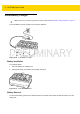
6 - 14 WT6000 User Guide Figure 6-14 2. Insert WT6000 into Cradle Ensure that the WT6000 is properly seated in the charging slot. Battery Charging The WT6000 Charging LED indicates the charging status of the battery in the WT6000. See Table 6-2 on page 6-5. The 3,350 mAh battery fully charges in less than four hours at room temperature. Charge batteries in temperatures from 0 °C to 40 °C (32 °F to 104 °F). The battery charger always performs battery charging in a safe and intelligent manner.
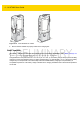
Accessories 6 - 15 5-Slot WT6000 Ethernet Cradle NOTE Ensure that you follow the guidelines for battery safety described in Battery Safety Guidelines on page 7-1. The 5-Slot WT6000 Ethernet Cradle: • Provides 5.4 VDC (nominal) power for operating the WT6000. • Connects up to five WT6000 devices to an Ethernet network. • Simultaneously charges up to five WT6000 devices. • Simultaneously charges up to five spare batteries.
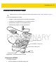
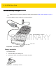
6 - 16 WT6000 User Guide Figure 6-16 2. Insert WT6000 into Cradle Ensure that the WT6000 is properly seated in the charging slot. Charging the Spare Battery 1. Insert a spare battery into the spare battery slot. Figure 6-17 2. Insert Battery into Cradle Ensure the battery is seated properly. The Spare Battery Charging LED blinks indicating charging.
Accessories 6 - 17 1. Touch . 2. Touch Ethernet. 3. Slide the Ethernet switch to the ON position. 4. Insert the device into a slot. 5. The 6. Touch Eth0 to view Ethernet connection details. icon appears in the Status bar. Ethernet LED Indicators There are two green LEDs on the side of the cradle. These green LEDs light and blink to indicate the data transfer rate.
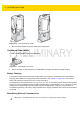
6 - 18 WT6000 User Guide 4-Slot Battery Charger NOTE Ensure that you follow the guidelines for battery safety described in Battery Safety Guidelines on page 7-1. The 4-Slot Battery Charger charges up to four spare batteries. Power LED Battery Charging LEDs (4) Figure 6-18 4-Slot Battery Charger Battery Installation To install the battery: 1. Insert the battery into a battery slot. 2. Gently press down on the battery until it snaps into place.
Accessories 6 - 19 Battery Charging Spare Battery Charging Each Battery Charging LED indicates the status of the battery charging in each slot. See Table 6-2 on page 6-5. The 3,350 mAh battery fully charges in less than four hours at room temperature. Charge batteries in temperatures from 0 °C to 40 °C (32 °F to 104 °F). The battery charger always performs battery charging in a safe and intelligent manner. At higher temperatures (e.g.
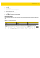
6 - 20 WT6000 User Guide 20-Slot Battery Charger NOTE Ensure that you follow the guidelines for battery safety described in Battery Safety Guidelines on page 7-1. The 20-Slot Battery Charger charges up to 20 spare batteries. Battery Charging LEDs (20) Power LED Figure 6-20 20-Slot Battery Charger Battery Installation To install the battery: 1. Insert the battery into a battery slot. 2. Gently press down on the battery until it snaps into place.
Accessories 6 - 21 Battery Removal To remove the battery, press the two release latches on each side of the battery and lift the battery out of the battery slot. Battery Charging Spare Battery Charging Each Battery Charging LED indicates the status of the battery charging in each slot. See Table 6-2 on page 6-5. The 3,350 mAh battery fully charges in less than four hours at room temperature. Charge batteries in temperatures from 0°C to 40°C (32°F to 104°F).
6 - 22 WT6000 User Guide USB and Charging Cable NOTE Ensure that you follow the guidelines for battery safety described in Battery Safety Guidelines on page 7-1. The USB and Charging cable connects to either interface connector on the WT6000. When attached to the WT6000, allows the WT6000 to transfer data to a host computer and provide power for charging the WT6000. Power Connector WT6000 Connector Figure 6-22 USB Connector USB and Charging Cable Attaching the USB and Charging Cable 1.
Accessories 6 - 23 2. Attach the USB connection to the host computer. Removing the USB and Charging Cable To remove the USB and Charging cable: 1. Press the release level toward the cable. 2. Rotate the adapter toward the front of the device and remove. Battery Charging To charge the WT6000, attached the power cable to the Power Connection on the USB and Charging Cable. Main Battery Charging The WT6000 Charging/Scan LED indicates the status of the battery charging in the device.
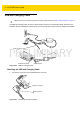
6 - 24 WT6000 User Guide Quick Disconnect Audio Cables The Quick Disconnect Audio Adapter snaps into either interface connector. When attached to the WT6000, the Quick Disconnect Audio Adapter allows a user to connect a wired headset to the WT6000. Long Audio Cable Figure 6-24 Short Audio Cable Audio Cables Attaching the Audio Adapter 1. Align the tabs on the Audio Adapter with the slots on the device. 2. Rotate the Adapter toward the back of the device until the Adapter snaps onto the device.
Accessories 6 - 25 Connecting the Audio Cable to a Headset Short Audio Cable Figure 6-26 Short Quick Disconnect Audio Cable Connection to Headset Removing the Audio Adapter To remove the Audio Adapter: 1. Press the release level toward the cable. 2. Rotate the adapter toward the front of the device and remove.
6 - 26 WT6000 User Guide Vibrator Cable Use the Vibrator cable to provide a touch notification to a user to in noisy environments. Figure 6-27 Vibrator Cable Connect the cable to the Interface connector on the WT6000. Slide the vibrator end between the Wrist Mount strap and arm. Figure 6-28 Connecting Vibrator Cable to WT6000 When an application generates a notification, the vibrator vibrates notifying the user.
Accessories 6 - 27 RS4000 Scanner To connect the RS4000 scanner to the WT6000: NOTE There are two scanner configurations available. The short cable configuration connects the scanner to the WT6000 mounted on the arm. The extended cable configuration connects the scanner to the WT6000 mounted on the hip. 1. Connect the scanner interface cable to the WT6000 interface connector. If the WT6000 is mounted on the arm, connect the cable to the interface connector closest to the wrist.
6 - 28 WT6000 User Guide 4. Slide the scanner onto the index finger with the scan trigger next to the thumb. Figure 6-31 5. Tighten the finger strap. Figure 6-32 6. Place the Scanner on Index Finger Tightening Straps If required, cut excess finger strap material. After connecting the scanner, warm boot the WT6000. See Resetting the Wearable Terminal on page 2-19 for information on performing a warm boot.
CHAPTER 7 MAINTENANCE AND TROUBLESHOOTING Introduction This chapter includes instructions on cleaning and storing the WT6000, battery maintenance and provides troubleshooting solutions for potential problems during WT6000 operations. Maintaining the WT6000 For trouble-free service, observe the following tips when using the WT6000: • Protect the WT6000 from temperature extremes. • Do not store or use the WT6000 in any location that is extremely dusty, damp, or wet.
7-2 WT6000 User Guide • Do not disassemble or open, crush, bend or deform, puncture, or shred. • Severe impact from dropping any battery-operated device on a hard surface could cause the battery to overheat. • Do not short circuit a battery or allow metallic or conductive objects to contact the battery terminals. • Do not modify or remanufacture, attempt to insert foreign objects into the battery, immerse or expose to water or other liquids, or expose to fire, explosion, or other hazard.
Maintenance and Troubleshooting 7 - 3 hydrocarbons; acqueous or alcoholic alkaline solutions; ethanolamine; toluene; trichloroethylene; benzene; carbolic acid, and TB-lysoform, bleach products and hydrogen peroxide. Cleaning Instructions Do not apply liquid directly to the device. Dampen a soft cloth or use pre-moistened wipes. Do not wrap the device in the cloth or wipe, but gently wipe the unit. Be careful not to let liquid pool around the display window or other places.
7-4 WT6000 User Guide 4. Repeat at least three times. 5. Use the cotton tipped applicator dipped in alcohol to remove any grease and dirt near the connector area. 6. Use a dry cotton tipped applicator and repeat steps 3 through 5. 7. Spray compressed air on the connector area by pointing the tube/nozzle about ½ inch away from the surface. CAUTION 8. Do not point nozzle at yourself and others, ensure the nozzle or tube is away from your face.
Maintenance and Troubleshooting 7 - 5 ComfortPad Carriage Strap Figure 7-1 Wrist Mount Remove the strap and comfort pad from the wrist mount. Hand wash in cold water with a mild detergent (such as Woolite®). Do not use bleach. Air dry. Do not use a dryer.
7-6 WT6000 User Guide Figure 7-3 Strap Figure 7-4 Carrier
Maintenance and Troubleshooting 7 - 7 Troubleshooting WT6000 Table 7-1 Troubleshooting the WT6000 Problem WT6000 does not turn on. Cause Solution Battery not charged. Charge or replace the battery in the WT6000. Battery not installed properly. Ensure battery is installed properly. See Installing the Battery on page 1-3. System crash. Perform a soft reset. If the WT6000 still does not turn on, perform a hard reset. See Resetting the WT6000 on page 2-11. Battery failed. Replace battery.
7-8 WT6000 User Guide Table 7-1 Troubleshooting the WT6000 (Continued) Problem Cause A message appears stating that the WT6000 memory is full. Too many files stored on the WT6000. Delete unused memos and records. You can save these records on the host computer. Too many applications installed on the WT6000. If you have installed additional applications on the WT6000, remove them to recover memory. The WT6000 does not accept scan input. Unreadable bar code. Ensure the symbol is not defaced.
APPENDIX A SPECIFICATIONS Technical Specifications The following tables summarize the WT6000’s intended operating environment and general technical hardware specifications. Table A-1 Technical Specifications Item Description Physical and Environmental Characteristics Dimensions (H x L x W) 121 mm x 89mm x 34 mm 4.8 in. x 3.5 in. x 1.3 in. Weight 245 g (8.7 oz.) Display Color Transflective LCD Display and IPS Technology, 3.2 in.
A - 2 WT6000 User Guide Table A-1 Technical Specifications (Continued) Item Description Memory 1 GB RAM, 4 GB Flash (pSLC) Application Development Zebra Android EMDK User Environment Operating Temperature -30°C to 50°C (-22°F to 122°F) Storage Temperature -40°C to 70°C (-40°F to 158°F) Battery Charging Temperature 0°C to +40°C (32°F to 104°F) ambient temperature range. Humidity 5% - 95% non-condensing Drop Specification 1.2 m (4 ft.
Specifications A - 3 Table A-1 Technical Specifications (Continued) Item Description Data Capture Laser Scanning Optional RS4000 laser scanner. Imager Optional Rs507 and RS6000 ring scanners. NFC Multi-Protocol NFC (optional).
A - 4 WT6000 User Guide
INDEX Numerics Numerics 1-D bar codes . . . . . . . . . . . . . . . . . . . . . . . . . . . . . . 3-1 2-D bar codes . . . . . . . . . . . . . . . . . . . . . . . . . . . . . . 3-1 A accessories . . . . . . . . . . . . . . . . . . . . . . . . . . . . . . . . 6-1 airplane mode . . . . . . . . . . . . . . . . . . . . . . . . . . . . . 1-13 android version . . . . . . . . . . . . . . . . . . . . . . . . . . . . . . xii applock administrator . . . . . . . . . . . . . . . . . . . . . . . .
Index - 2 WT6000 User Guide imaging . . . . . . . . . . . . . . . . . . . . . . . . . . . . . . . . . . . 3-2 information, service . . . . . . . . . . . . . . . . . . . . . . . . . . .xiv K set time zone . . . . . . . . . . . . . . . . . . . . . . . . . . . . . . 1-13 settings . . . . . . . . . . . . . . . . . . . . . . . . . . . . . . . . . . . 2-8 sound recorder . . . . . . . . . . . . . . . . . . . . . . . . . . . . . . 2-9 starting the mobile computer . . . . . . . . . . . . . . . . . . .
Zebra Technologies Corporation, Inc. 3 Overlook Point Lincolnshire, IL 60069, U.S.A. http://www.zebra.com Zebra and the stylized Zebra head are trademarks of ZIH Corp., registered in many jurisdictions worldwide. All other trademarks are the property of their respective owners. © 2016 Symbol Technologies LLC, a subsidary of Zebra Technologies Corporation. All Rights Reserved.