
User's Manual


User Guide
___________________________________________________________________________________________________________________
_________________________________________________________________________________________________________________
19
User Guide, WherePort IV D1300 REV A
© Copyright WhereNet, Corp. 2008 WhereNet Confidential
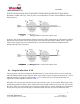
Figure 12 Orientation and Capture Area
Two maps are shown for two different WherePort IV mountings, horizontal (left) and vertical (right).
The two maps show two different tag orientations for each of the mountings.
Figure 12 shows the effects of WherePort IV and Tag orientation on the guaranteed capture area. These
maps are taken from the Simulation software.
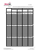
7.3. Power Level
The size of the field is determined by the power setting for the WherePort IV. There are 31 power levels
for the WherePort IV. Setting the power level to 0 turns off the WherePort IV magnetic field. Table 3
shows the approximate capture and release ranges for each of the power levels when the tag’s orientation
is random and when it is fixed as it moves through the field.