User Guide ___________________________________________________________________________________________________________________ User Guide, WherePort IV Document Number D1300 Document Revision History Revision A Description of Change Release per ECO C01554 Date Approved 08/12/08 D. Olsen _________________________________________________________________________________________________________________ User Guide, WherePort IV © Copyright WhereNet, Corp.
User Guide ___________________________________________________________________________________________________________________ TABLE OF CONTENTS 1.0 SCOPE 6 2.0 NOTICES AND REQUIREMENTS 6 2.1. FCC AND IC REQUIREMENTS 6 2.2. EUROPE R&TTE DIRECTIVE 1999/5/EC REQUIREMENTS 6 2.3. RF NOTICE 6 3.0 APPLICABLE DOCUMENTS 7 4.0 EQUIPMENT AND ACCESSORIES 7 5.0 SYSTEM OVERVIEW 7 5.1. THIS GUIDE 9 5.2. THE WHEREPORT IV 9 5.3. HEALTH TAG 10 5.4.
User Guide ___________________________________________________________________________________________________________________ 7.11. CAPTURE AREA SIMULATOR 27 WHEREPORT IV IN THE FIELD 28 8.1. ZONES 28 8.2. AREA COVERAGE 29 8.3. PORTALS 29 8.4. MULTI-FLOOR INSTALLATIONS 32 8.5. LOCKED WHEREPORT IVS 32 8.6. MULTIPLE WHEREPORT IVS 33 8.7. SEQUENCED WHEREPORT IVS 37 8.8. SUMMARY 37 WORKING THRU AN APPLICATION 38 9.1. WAREHOUSE AND SHIPPING FACILITY 39 9.2.
User Guide ___________________________________________________________________________________________________________________ 12.5.5. TAG ID 56 12.5.6. RESPONSE 56 12.5.7. COUNT 56 12.5.8. INTERVAL 57 12.5.9. TRIGGER 57 12.5.10. DATA 57 12.5.11. EXE 58 12.5.12. SEQUENCE MODE 58 12.5.13. SEQUENCE MODE MESSAGE NUMBER 58 12.5.14. VERSION 59 12.5.15. XPW 59 12.5.16. HWT (1) 59 12.5.17. LOADER 59 12.5.18.
User Guide ___________________________________________________________________________________________________________________ List of Figures Figure 1 Figure 2 Figure 3 Figure 4 Figure 5 Figure 6 Figure 7 Figure 8 Figure 9 Figure 10 Figure 11 Figure 12 Figure 13 Figure 14 Figure 15 Figure 16 Figure 17 Figure 18 Figure 19 Figure 20 Figure 21 Figure 22 Figure 23 Figure 24 Figure 25 Figure 26 Figure 27 Figure 28 Figure 29 Figure 30 WherePort IV ...............................................................
User Guide ___________________________________________________________________________________________________________________ 1.0 SCOPE To provide a RTLS system overview and give some magnetic communication background information relevant to the WherePort IV function. This guide shows the application of a WherePort IV device in the field in association with tags and shows an application example and also shows the use of a simulator tool to analyze the field pattern. The command summary is also reviewed.
User Guide ___________________________________________________________________________________________________________________ 3.0 APPLICABLE DOCUMENTS The following documents, latest revision, form a part of this document to the extent specified herein. In the event of conflict the documents listed below shall govern. • • • 4.0 WherePort IV Instruction Sheet, WherePort IV, Installation Outline Drawing, WherePort IV EQUIPMENT AND ACCESSORIES • • • • 5.
User Guide ___________________________________________________________________________________________________________________ Status LED Figure 1 WherePort IV The VSS system is programmed with the location of each WherePort IV and their ID. When a WhereTag transmits a message that includes the ID of the WherePort IV field that it is in, the system knows where the WhereTag is.
User Guide ___________________________________________________________________________________________________________________ 5.1. This Guide This guide presents the basic principles of WherePort IV communication and the major issues for placing them on a site. It is intended to support both the planning for and the implementation of an RTLS application using WherePort IVs.
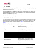
User Guide ___________________________________________________________________________________________________________________ AC/48VDC Adapter Power over Ethernet RJ-45 Sync In Sync Out RJ-11 Slave 2 Sync In Sync Out RJ-11 Slave 1 Figure 2 RJ-45 POE Master Wiring Schematic for Power and Synchronization Each 48 VDC Adapter supports one WherePort IV. 5.3. Health Tag A WhereTag that is programmed to blink when there is no signal from the WherePort IV may be mounted to each WherePort IV.
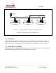
User Guide ___________________________________________________________________________________________________________________ Mounting Bracket Figure 3 6.0 WherePort IV Mounting Bracket THE WHERETAG The WhereTag (Figure 4) is pinged by the WherePort IV and responds by transmitting a data message to the RTLS. The WhereTag is a small device with a magnetic pick up coil and a RF transmitter. It is mounted to movable assets such as trailers, vehicle assemblies, or storage bins.
User Guide ___________________________________________________________________________________________________________________ Coil Orientation Figure 4 The WhereTag III and WhereTag III ST The solid line shows the orientation of the pick up coil for both WhereTags. 6.1. WhereTag Responses The tag can be programmed to respond in a variety ways when it detects a WherePort IV signal. There are three defined modes (see Figure 5).
User Guide ___________________________________________________________________________________________________________________ Figure 5 The WhereTag in a WherePort IV Capture Area In mode 1, the re-trigger is set for a time interval after the WherePort IV blink. When this interval elapses, the tag will transmit a blink if the tag is still in the same WherePort IV field. Without the retrigger interval being set, the tag will continue blinking in response to the WherePort IV signal.
User Guide ___________________________________________________________________________________________________________________ In mode 2 the tag must both leave the WherePort IV field and the specified interval elapse before a WherePort IV blink will occur. If the tag enters a new WherePort IV field it will immediately transmit a blink (Figure 2).
User Guide ___________________________________________________________________________________________________________________ Table 2 WherePort IV IDs ID Range Tag Response Standard WP Response Added Function 0 - 127 128 - 255 256 - 32,767 32,768 - 65,534 65,535 Yes Yes Yes Yes (ID - 32,768 reported) Yes + Exit Alternate Blink Mode Enter Alternate Blink Mode Response is data register _________________________________________________________________________________________________________________ Us
User Guide ___________________________________________________________________________________________________________________ 7.0 MAGNETIC COMMUNICATION BASICS The WherePort IV signal is carried by a magnetic field. The field’s shape and size is determined by the orientation of the coil and the power level. It is not possible to aim the field. One of the characteristics of a magnetic field is that it drops off rapidly. This produces a well-defined, localized field.
User Guide ___________________________________________________________________________________________________________________ Perpendicular Coils Parallel Coils Figure 10 Orientation When the coil in the tag and the port are parallel the range is the greatest. When the coils are perpendicular the range is the shortest. The relative positions of the two coils, WherePort IV transmitting and WhereTag receiving, determine the range in which the tag will receive the signal.
User Guide ___________________________________________________________________________________________________________________ 7.2. Coverage Areas The size of the coverage area is significant as well as its location or placement. It is important that the tag be released from a field when it is no longer in the area being monitored by the WherePort IV. There are three areas that are described for the field. Guaranteed Capture All WhereTags at a given orientation will always be pinged in this area.
User Guide ___________________________________________________________________________________________________________________ Figure 12 Orientation and Capture Area Two maps are shown for two different WherePort IV mountings, horizontal (left) and vertical (right). The two maps show two different tag orientations for each of the mountings. Figure 12 shows the effects of WherePort IV and Tag orientation on the guaranteed capture area. These maps are taken from the Simulation software. 7.3.
User Guide ___________________________________________________________________________________________________________________ Table 3 Power Levels, Random and Optimum Fixed Tag Orientations Power Level Capture Range Random Optimum Release Range Random Fixed Optimum Fixed 0 Off Off Off Off 1 1.0 2.2 3.5 3.5 2 1.2 2.5 4.0 4.0 3 1.3 2.7 4.5 4.5 4 1.5 3 4.7 4.7 5 1.6 3.2 5.0 5.0 6 2 4 6.0 6.0 7 2.2 4.5 7.0 7.0 8 2.3 4.7 7.5 7.5 9 2.5 5.0 8 8 10 2.
User Guide ___________________________________________________________________________________________________________________ Random orientation means that the tag may take any of the possible positions relative to the WherePort IV. Fixed tag orientation means that the motion of the object to which the tag is attached will always present the tag in the same position relative to the WherePort IV. A major difference between the random and the fixed orientation is the size of the uncertainty area.
User Guide ___________________________________________________________________________________________________________________ A WherePort IV set to 0º phase is defined as the master and all the other WherePort IVs are then connected to it using the phase wire connections. Phased WherePort IVs must all have the same ID. 90º 0º Master 180 º 270 º Figure 14 Phase and WherePort IV Orientation 7.6. Sequencing WherePort IVs that have been connected electronically can also operate in the sequence mode.
User Guide ___________________________________________________________________________________________________________________ Inactive Active Master WP #1 Slave WP #2 Slave WP #3 Figure 15 Mode 1 One WherePort IV is active at a time. A master and two slaves are shown. WhereWand WPSeq Count (or RS232 CMWn) = 2. Master WP #1 Slave WP #2 Slave WP #3 Slave WP #4 Figure 46 Mode 2 More than one WherePort IV may be active at a time. A master and three slaves are shown.
User Guide ___________________________________________________________________________________________________________________ Master WP #1 Slave WP #2 Figure 57 Mode 3 All WherePort IVs may be off part of the time. A master and one slave are shown. One is active, then two, then both are inactive. WhereWand WPSeq Count (or RS232 CMWn) = 2 or higher. With sequencing, WherePort IVs that might have conflicting fields if they were on at the same time, can be placed to indicate position or transitions.
User Guide ___________________________________________________________________________________________________________________ A B Figure19 C Coverage Pattern A single (A), adjacent (B), and dual WherePort IV (C) field are shown. The fields shown are for WherePort IVs at power level 8 and mounted at the same height as the WhereTag. 7.8. Interference Steel objects and some devices can interfere with the WherePort IV field and change its shape and range.
User Guide ___________________________________________________________________________________________________________________ Figure 20 Magnetic Field Meter 7.9. The Field Meter The field meter is a WhereTag connected to a voltage meter so that it can detect and display the strength of the WherePort IV field (Figure 20). By walking around an installed WherePort IV the strength of the signal throughout the area to be monitored can be measured.
User Guide ___________________________________________________________________________________________________________________ 7.10. The WherePort IV LED On the top of the WherePort IV is an LED that indicates the status of the WherePort IV (see Table 4). Table 4 7.11.
User Guide ___________________________________________________________________________________________________________________ 8.0 WHEREPORT IV IN THE FIELD The basic principles of the WherePort IV must be translated into applications in the field. Doors, corridors, rooms, parking lots do not necessarily conform to the requirements of the WherePort IV field.
User Guide ___________________________________________________________________________________________________________________ 8.2. Area Coverage There may, however, be many areas where different activities occur that must be monitored. Well positioned WherePort IVs can define these areas of interest by pinging tagged assets as they enter them. Examples are assembly stations in a factory, loading docks, or different types of rooms in a hospital.
User Guide ___________________________________________________________________________________________________________________ Corridor Functional Area Figure 82 WherePort IV in a Doorway To enter the room, an object must pass through the guaranteed capture range of the WherePort IV. The placement of a WherePort IV in the doorway might seem simple. Figure 82 shows this installation. Any tagged asset passing through the doorway must pass through the guaranteed capture range.
User Guide ___________________________________________________________________________________________________________________ Figure 93 Loading Dock Doors Spacing of loading dock doors makes it impossible to assign unique WherePort IV IDs to each of the doors. If, instead of a single door, a series of doors (for example on a loading dock) or bays are too close together, the fields may overlap so that it is not possible to assign a unique WherePort IV ID to each of the doors.
User Guide ___________________________________________________________________________________________________________________ Drop Ceiling Floor 2 Utility Space Drop Ceiling Floor 1 Figure 104 Multi-Floor Schematic Shows a floor configuration so that the WherePort IV field extends into the second floor. 8.4. Multi-Floor Installations When activities are tracked on several floors, the vertical position of the WherePort IV and the extent of its field must be carefully considered.
User Guide ___________________________________________________________________________________________________________________ Where room coverage is needed the RTLS algorithm could indicate that a tag is outside a room when it is not. WherePort IVs are defined as locked using the software of the SystemBuilder. No setting in the WherePort IV is needed. After a tag pings that it has detected a locked WherePort IV the tag will be ignored until it is unlocked.
User Guide ___________________________________________________________________________________________________________________ 0º Master 180 º Figure 115 Phasing for Wall Mounted WherePort IVs Viewed from the top. Figure 115 shows a corridor or large space with WherePort IVs mounted on the different walls to effectively cover the entire area. This means that the phase of each WherePort IV must be set as indicated.
User Guide ___________________________________________________________________________________________________________________ 90 º 0º Master Figure 126 180 º Phasing for Ceiling and Wall WherePort IVs A large doorway may require three WherePort IVs to reliably detect the passage of a tagged asset through it. In the example shown in Figure 126 coverage requires a WherePort IV on each side of the doorway and on the ceiling. Again each WherePort IV must be phased accordingly.
User Guide ___________________________________________________________________________________________________________________ Figure 137 and Figure 148 show two ways of solving the problem. The example in Figure 137 uses a WherePort IV to cover two doors. Since these WherePort IVs are mounted in different orientation on the walls, their phases must be set as well. Figure 148 shows a WherePort IV mounted above each door.
User Guide ___________________________________________________________________________________________________________________ 1 Figure29 3 2 4 Sequenced WherePort IVs on Parking Lanes 8.7. Sequenced WherePort IVs Figure29 shows the use of sequenced WherePort IVs to accurately identify which lane a vehicle has entered. Sequenced WherePort IVs are turned on and off. WherePort IVs 1 and 3 are on while 2 and 4 are off and then 2 and 4 are on while 1 and 3 are off.
User Guide ___________________________________________________________________________________________________________________ 9.0 WORKING THRU AN APPLICATION To effectively place WherePort IVs the site and the required information from the site must be carefully studied. In this chapter a simple site will be presented and issues about WherePort IV placement will be discussed and mounting locations for WherePort IVs found. Note that this study is regarding an outdoor application.
User Guide ___________________________________________________________________________________________________________________ 9.1. Warehouse and Shipping Facility Events or positions that need to be monitored in some way. What must be tracked. Trailers entering the yard Trailers at the loading dock Trailers in the waiting, parking area Trailers leaving the yard Issues affecting the placement of the WherePort IV.
User Guide ___________________________________________________________________________________________________________________ Figure 161 WherePort IVs Mounted on the Site _________________________________________________________________________________________________________________ User Guide, WherePort IV © Copyright WhereNet, Corp.
User Guide ___________________________________________________________________________________________________________________ 9.2.
User Guide ___________________________________________________________________________________________________________________ 10.0 USING THE SIMULATOR The WherePort IV simulator (WhereNet p/n D0910) is a tool for exploring the best solutions for WherePort IV placement and for better understanding the basic characteristics of WherePort IV communication.
User Guide ___________________________________________________________________________________________________________________ The magnetic field extends in all directions from the WherePort IV. Its position does, however, affect the direction of the field and therefore its relation to the position of the tag. It is the direction of the field that is important when reviewing the different orientations of the WherePort IV. Figure 183 10.2.
User Guide ___________________________________________________________________________________________________________________ Figure 194 Tag Orientations for the Graphs The graphs are calculated based on the tags maintaining the same orientation while it moves. Its orientation to the field will therefore change. For each WherePort IV position, graphs are drawn for six different WhereTag orientations.
User Guide ___________________________________________________________________________________________________________________ Figure 205 Sample Graph The graph shows the guaranteed capture area in green and the uncertainty area in yellow for a single WherePort IV, mounted horizontally, with a power level of 4, and a tag to WherePort IV height of 4 feet for a tag with orientation 2. The scale is 10.
User Guide ___________________________________________________________________________________________________________________ Figure 216 Sample Graph Shows the same configuration as Figure 4 except the tag is in the 6 orientation. 10.3. Sample Graphs The importance and usefulness of the simulator can be shown by looking at two graphs showing two different tag orientations while all other options are identical.
User Guide ___________________________________________________________________________________________________________________ Figure 227 Power Level Comparison Tag Orientation 2 _________________________________________________________________________________________________________________ User Guide, WherePort IV © Copyright WhereNet, Corp.
User Guide ___________________________________________________________________________________________________________________ Figure 238 Power Level Comparison Tag Orientation 6 _________________________________________________________________________________________________________________ User Guide, WherePort IV © Copyright WhereNet, Corp.
User Guide ___________________________________________________________________________________________________________________ Figure 39 10.4. Adjacent WherePort IV Configuration Adjacent WherePort IVs Adjacent WherePort IVs require that some additional variables be set: Power Level Select a power lever from 1 to 8. The highest power level is 8. Note that the WP4 power level has 31 steps with 31 as the max.
User Guide ___________________________________________________________________________________________________________________ 11.0 GLOSSARY blink A signal sent by a WhereTag to the RTLS system. A blink may contain 1 to 8 sub-blinks. coverage area The area in which a WhereTag will be pinged by a WherePort IV signal. dual WherePort IV Two WherePort IVs on a bracket, oriented at 90 degrees to each other.
User Guide ___________________________________________________________________________________________________________________ slave All WherePort IVs other than the maser in a group of sequenced or phased WherePort IVs. uncertainty area The part of the WherePort IV field where a tag may be pinged but where it is also possible that it will not be pinged. WherePort IV ID A number from 0 to 32,000 that identifies each WherePort IV to the system.
User Guide ___________________________________________________________________________________________________________________ 12.0 COMMAND SUMMARY This appendix describes the commands used to configure the WherePort IV. • All commands and responses are ASCII character strings. • ACK responses are the three character string ‘ACK’ and not the 0x06 non-printable character. Similarly, NAK responses are the three character string ‘NAK’ and not the 0x15 non-printable character.
User Guide ___________________________________________________________________________________________________________________ The password can be set using the ****:XPW **** command. Changes to the password will take effect immediately. The changes affect only the current session unless the host sends the WherePort IV an execute command (****:EXE). Only after receiving an execute command will the new password be written into flash memory and read on power up.
User Guide ___________________________________________________________________________________________________________________ 12.5. Commands 12.5.1. Message Length Set the length, in bits, of the WherePort IV message. There are six possible values. n Value 1 10 bit 2 28 bit 3 44 bit 4 144 bit 5 144 bit with payload CRC1 6 144 bit with payload CRC2 Example: MSG 1 Sets the message length to 10 bits. Considerations: Message length affects the dwell time when using sequenced WherePort IVs.
User Guide ___________________________________________________________________________________________________________________ 12.5.3. Phase Set the phase. PHS n Valid range for n is 0 through 3 where 0 equals 0º, 1-90 º, 2-180 º, and 3-270 º. Example: PHS 2 Sets the phase to 2. Considerations: When WherePort IV fields overlap, the phase of each WherePort IV must be set to match to placement of the ports. 12.5.4. WherePort IV ID Sets the WherePort IV Id. The valid range is 0 to 32,767.
User Guide ___________________________________________________________________________________________________________________ 12.5.5. Tag Id Set the tag ID: (for 144 bit messages only). The valid range is 0 to 4,294,967,295. TID n Example: TID 4 Sets the tag id to 4. Considerations: The tag ID is only set using a 144 bit message. 12.5.6.
User Guide ___________________________________________________________________________________________________________________ Example: CNT 4 Sets the blink count to 4. 12.5.8. Interval Set the WherePort IV response blink interval (44 bit message only ) where n is 0 to 7. INT n 12.5.9. Trigger Set the re-trigger response (44 bit message only). TRG n Where n is a value 0 through 15. Example: TRG 4 Sets the re-trigger response to 10 sec. 12.5.10.
User Guide ___________________________________________________________________________________________________________________ 12.5.11. EXE EXE n Send message to magnetic field generator and the flash memory. 12.5.12. Sequence Mode Set number of WherePort IV in the chain for sequencing mode. CMW n Where n is a value of 1 through 15. A value of 0 disables sequence mode. A value of 1 means that there is a master and 1 slave.
User Guide ___________________________________________________________________________________________________________________ 12.5.14. Version Set the software version number. VER m.nn Where m is the major version and nn is the minor version. Example: VER 2.01 Sets the WherePort IV software version number to 2.01. 12.5.15. XPW Set the password to the four character ssss. XPW ssss 12.5.16. HWT (1) Used to test the ISP port pins and set the WherePort IV password access flags.
User Guide ___________________________________________________________________________________________________________________ GQ1 Set message length = 10 bit Execute immediately GQ1 n Set WPID = n, where 0 ≤ n ≤ 7 Set message length = 10 bit Execute immediately GQ2 Set message length = 28 bit Execute immediately GQ2 n Set WPID = n, where 0 ≤ n ≤ 32,767 Set message length = 10 bit Execute immediately GQ3 n,m,p,q n = 0x0-0x7FFF m = 0x0-0xF p = 0x1-0x7 q = 0x0-0xF Arguments are in upper case ASCII-H
User Guide ___________________________________________________________________________________________________________________ GQ4 n,s n = 0 to 7FFF s = string Set message length = 144 bit (CRC) Set Tag ID = n Set data string = s (22 or 24 chars) Execute immediately GQ5 n N = 0 to 7FFF Set message length = 144 bit (CRC) Set Tag ID = n Execute immediately GQ5 s Set message length = 144 bit (CRC) Set data string = s (22 or 24 chars) Execute immediately GQ5 n,s n = 0 to 7FFF s = string Set message leng