
Installation Guide

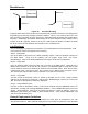

Table Of Contents
- Overview
- Description of the MEA System
- Introduction
- Subscriber Devices (SDs)
- Wireless Routers (WRs)
- Intelligent Access Points (IAPs)
- VMM6300 - Vehicle Mounted Modem
- EWR6300 - Enhanced Wireless Router
- PWR6300 Portable Wireless Router
- Mobile Internet Switching Controller (MiSC)
- Operational View of the MEA System
- Network Architecture
- Unified Modes of Operation
- Quality of Service (QoS) and User Priority Features
- Setup and Installation
- Subscriber Device (SD)
- Intelligent Access Point (IAP)
- Wireless Router (WR)
- Mobile Internet Switching Controller (MiSC)
- Upgrade MiSC/DHCP Configuration (optional)
- MAC Address Tables
- Site Selection/Deployment Guidelines
- Customer Service Information
- License and Warranty Information
- FCC Regulatory Information
- Safety Information for the MEA Products
- Safety Certification

MeshNetworks
Obstruction
Antenna
Antenna
Obstruction
Figure 40. Antenna Mounting
Low gain rubber duck antennas that are mounted directly to Mesh transceivers are designed for
transmitting and receiving vertically polarized radiation. Hence, care must be taken to insure
close-to-vertical orientation of these antennas to avoid substantial signal loss due to polarization
mismatch. Additionally, attenuation sustained by use of these antennas inside vehicles can be
as high as 10 dB. Typically, losses are in the 4 to 7 dB range if the antenna is above the metal
can of the vehicle so that radiation and reception occur at window level.
Lab Checkout
Prior to deploying any equipment in the field, it is recommended to test the equipment in a lab
environment to ensure the equipment is functioning.
Step 1 - Verify MiSC
Set up the MiSC as discussed in the MiSC Assembly section. Attach a Windows computer to
the SMC switch. Verify that the following can be pinged: edge router, core router,
MeshManager. Refer to the Default Addresses and Logins section for the addresses.
Step 2 – Verify IAPs.
Using an Ethernet cable, attach the IAPs, one at a time, to the SMC switch. Using either the
MAC or ETH address on the IAP box for reference, use MeshManager to verify that the IAP
can be reached, and that it is obtaining an address from the DHCP server. Next, start an SD in
infrastructure mode, and ensure that it also receives an IP address from the DHCP server.
This verifies that both the SBC and the transceiver in the IAP are functioning.
Step 3 – Verify WRs
Connect an IAP as described in Step 2. Power up the WRs one at a time. Using the MAC
address on the WR box for reference, verify that the MeshManager console can reach each
WR, and that an appropriate IP address is displayed.
Step 4 – Verify PCMCIA cards
Connect an IAP as described in Step 2, Load a host computer with the WMC6300 drivers as
described in Loading and Verifying WMC6300 Software. Insert a WMC6300 card into the host
device. Start MeshTray. Verify that the status tab displays a valid IP address. Eject the
WMC6300 card utilizing the Unplug or Eject Hardware icon. Insert another WMC6300 card
and repeat the MeshTray test.
General Deployment Guidelines
It is recommended that field deployment follow the same steps as described in the Lab
Checkout Procedures. IAPs should be deployed first and verified as functional. Next the WRs
40