
Installation Guide

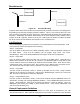

Table Of Contents
- Overview
- Description of the MEA System
- Introduction
- Subscriber Devices (SDs)
- Wireless Routers (WRs)
- Intelligent Access Points (IAPs)
- VMM6300 - Vehicle Mounted Modem
- EWR6300 - Enhanced Wireless Router
- PWR6300 Portable Wireless Router
- Mobile Internet Switching Controller (MiSC)
- Operational View of the MEA System
- Network Architecture
- Unified Modes of Operation
- Quality of Service (QoS) and User Priority Features
- Setup and Installation
- Subscriber Device (SD)
- Intelligent Access Point (IAP)
- Wireless Router (WR)
- Mobile Internet Switching Controller (MiSC)
- Upgrade MiSC/DHCP Configuration (optional)
- MAC Address Tables
- Site Selection/Deployment Guidelines
- Customer Service Information
- License and Warranty Information
- FCC Regulatory Information
- Safety Information for the MEA Products
- Safety Certification

MEA Setup and Installation
Section 5 - Site Selection/Deployment Guidelines
General Site Selection Guidelines
The IAP location(s) should be selected first since they have the additional requirement of routing
information back to the MiSC. This may be done via an Ethernet cable if the IAP and MiSC are
located within 100 meters (the max length permitted for standard Ethernet) of each other. If the
distance is greater than 100 meters, a mechanism for extending the Ethernet connection will be
required, e.g., using fiber or T1. (MeshNetworks recommends T1 backhaul equipment from
Net-to-Net Technologies.)
Once the IAPs have been placed, then the location of the WRs can be determined. Optimally,
the devices should be distributed such that a SD has no more than 3 hops to an IAP.
Power must be available for both IAPs and WRs. Both IAPs and WRs come standard with AC
power; DC power is available as an option.
Lastly, any local building/structure codes must be adhered to, as well as proper permits for
placing devices on structures that are not owned by the Network Operator (e.g., light poles).
MeshNetworks has developed the Location Analyzer tool to assist in the placement of
infrastructure. This tool runs on a Windows 2000 SD. The tool collects and analyzes data,
ultimately resulting in a deployment quality indication. Refer to the Location Analyzer
documentation for information on configuring and using this tool.
Antenna Guidelines
The location of fixed infrastructure antennas must address proper antenna orientation, selection
of elevation pattern for the specific locale, the avoidance of pattern distortion, and the impact of
obstructions and non-line-of-sight paths.
Polarization - Most of the antennas used in deployment will be vertically polarized. To maximize
line-of-sight signal reception, both the transmitting and receiving antennas should be vertically
oriented to avoid signal loss due to polarization mismatch. This applies to mobile and stationary
antennas. For example, placing a magnetically mounted vehicle antenna on a curved portion of
the vehicle roof so that its axis is not vertical risks a measure of signal loss at range, dependent
upon the specific elevation pattern details, as discussed above.
Local obstructions - Antennas should be mounted either above or below the plane of
obstructions as shown in Figure 40.
39