
Installation Guide
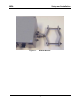
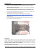
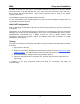
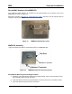
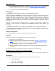
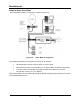
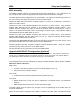
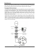
Table Of Contents
- Overview
- Description of the MEA System
- Introduction
- Subscriber Devices (SDs)
- Wireless Routers (WRs)
- Intelligent Access Points (IAPs)
- VMM6300 - Vehicle Mounted Modem
- EWR6300 - Enhanced Wireless Router
- PWR6300 Portable Wireless Router
- Mobile Internet Switching Controller (MiSC)
- Operational View of the MEA System
- Network Architecture
- Unified Modes of Operation
- Quality of Service (QoS) and User Priority Features
- Setup and Installation
- Subscriber Device (SD)
- Intelligent Access Point (IAP)
- Wireless Router (WR)
- Mobile Internet Switching Controller (MiSC)
- Upgrade MiSC/DHCP Configuration (optional)
- MAC Address Tables
- Site Selection/Deployment Guidelines
- Customer Service Information
- License and Warranty Information
- FCC Regulatory Information
- Safety Information for the MEA Products
- Safety Certification

MeshNetworks
Assemble the IAP using the following procedure:
1.
2.
3.
4.
5.
6.
If desired, mount the IAP6300 box using the enclosed bracket. Refer to Figure 11.
Place the bracket at the desired position on the pole The bracket can accommodate
pole diameters between 1-3.5 inches.
Adjust the position of the box so that the antenna will be in a vertical position. Tighten
the pivot and angle locking bolts on the shaft of the bracket as shown in Figure 12
Insert the antenna into the N-type Connector on the top of the box, and rotate to close.
Insert the IAP Power Plug into the 4-pin connector.
Install the weatherproof connector on the Ethernet cable as described at:
http://www.siemon.com/installation_instructions/pdf/IMAXIndustrialUTPPlug.pdf
7.
8.
9.
Insert the Ethernet Cable into the RJ-45 port and tighten the connector to ensure a
weatherproof seal.
If used, insert the Media Converter Power Cable into the optional 3-pin connector.
The Test Port is unused during deployment
6 x 32 x 3/4
Angle Locking Bolt
1/4 x 1 inch Pivot Bolt
(Requres 7/16 Wrench)
Figure 12. Bracket Adjustment Bolts
Deployment
The IAP may be mounted on a pole having a diameter of 1-3.5 inches, utilizing the provided
bracket. The antenna must have a separation distance of at least 2 meters from the body of all
persons and must not be co-located or operating in conjunction with any other antenna or
transmitter. Users and installers must be provided with antenna installation and transmitter
operating conditions to satisfy RF exposure compliance.
When deploying the IAP, the antenna should be a minimum of 30 inches from any nearby metal
poles to avoid distortion of the RF pattern.
The IAP must have an Ethernet connection to the MiSC. If the distance between the IAP and
8