
User's Manual
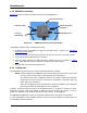

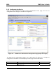
Table Of Contents
- Enhanced Wireless Router
- Installation Requirements
- Installing the MEA Enhanced Wireless Router
- Device Administration: Configuring the EWR Devices
- External Device Provisioning
- Infrastructure Requirements
- EWR6300 Mounting Bracket
- License and Warranty Information
- FCC Regulatory Information
- Safety Information for the MEA Products
- Safety Certification

MEA EWR User’s Guide
Figure 2-3 Typical EWR Depoyment
2.1.5 Deployment Tips
multipath:
rference from nearby transmitters
nnection to other
• nna supplied is designed to be mounted vertically
he devices are designed to be vertically mounted with the antenna port at the top or the
2.1.6 Initial Configuration
Location is the same as the setup for the IAP as described in
2.1.7 Testing
of the EWR6300 using the following procedure:
1. Apply power to the EWR6300.
dress and ETH address that was recorded in Section
Locate the antenna to minimize
• Minimize inte
• Maximize chance of a direct line of sight co
devices
The ante
T
bottom. The antenna is specified around deployment heights of 3-30 meters. Remotely locating
the antenna will degrade the performance through cable loss, though this may be mitigated by
better antenna positioning.
The configuration process for Geo-
the mea Setup and Deployment User’s Guide for Infrastructure Mode User’s Guide.
Verify the operation
2. Obtain the transceiver MAC ad
3.4.1. The address will be in the form of 00-05-12-0A-xx-yy.
3. he MAC address.
o test
communications with the device.
From the MeshManager user interface, display devices using t
4. Select the appropriate EWR in the device tree, right click and select ping t
5