
User's Manual
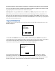
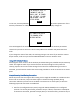
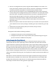
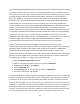
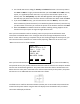
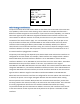
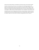
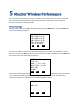
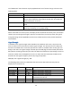
Table Of Contents
- 1 Introduction
- 2 Networking Basics
- 3 Installing Printer
- 4 Configuring the Printer
- Network Settings
- Configuring the Printer through the Operator Control Panel
- Configuring Wireless through the Printer Web Page
- Configuring Wireless through the Driver Toolbox
- Using ZXP Toolbox Wireless Settings Load/Save Buttons
- Using RADIO CONTROL Menu
- Using SET DEFAULTS Menu
- Simple Roaming Used During Connection
- Setting Up an Ad-Hoc (Peer) Network
- Multi-homing Considerations
- 5 Monitor Wireless Performance
- Wireless Info Pages
- Signal Strength
- Noise Floor
- Data Rate
- DHCP & MAC Address Info Page
- Wireless Statistics Info Page
- Wireless Statistics Success and Failure Rates
- Main Status Display Wireless Errors
- Viewing Wireless Information through Printer Web Page
- Viewing Wireless Information through Windows Printer Driver Toolbox
- 6 Troubleshooting
- 7 Technical Specifications
- 8 Glossary
- 9 Compliance Information

40
The “RADIO OFF” status location may be populated with one of several strings as shown in the
following table:
Radio Status
Description
RADIO OFF The radio is turned off.
RADIO DISCONNECTED The radio has not yet started the process of connecting to an access
point or the link with the access point has been lost. The radio will
shortly attempt to reconnect.
RADIO INACTIVE The radio is inactive because the association with an access point
failed.
RADIO CONNECTING The radio is in the process of connecting to an access point
(scanning, associating or key handshaking).
When connected to an access point, the display shows the SSID of the access point, the wireless
channel, the current signal strength in percent, the noise floor, the security mode, the type of
encryption being used (if applicable) and the current data rate that recent packets have been
received with.
Signal Strength
In addition to the signal strength value available on the Wireless Info screen, the printer also
uses an antenna icon on the OCP to indicate signal strength. The antenna icon has a body and
four bars associated with it. Thus five separate icon states are available from no bars (just icon
body) to four bars. The signal strength is based upon the SNR (Signal to Noise Ratio) with which
data packets are being received by the radio. The SNR is translated into a percentage in order to
make the number more intelligible to the user. For those that are interested, the SNR can be
derived from the signal strength in percent by using this equation:
SNR (dB) = 40 * Signal Strength (%) / 100
The following table outlines the SNR bands that are used to determine how many bars to
display for the antenna icon:
SNR (dB)
Bars
Signal
Strength %
Quality
40 and above
4
100
Robust connection, always fast.
25 to 39.99
3
62 - 99
Robust connection, mostly fast.
15 to 24.99
2
37 - 61
Robust connection, usually fast.
5 to 14.99 1 12 -36 Connection slow with packet resends and
intermittent loss of link.
0 to 4.99
0
0 - 11
Insufficient signal to connect.
0 - blinking Connection in progress.