
User's Manual


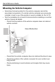


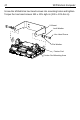
Table Of Contents
- Warranty
- Introduction
- About This Guide
- Features
- Unpacking
- Optional Accessories
- Installation
- Installing the VC70 on a Forklift
- Mounting the Vehicle Computer
- U Mount Installation
- Mounting onto an Over-Head Cross-Beam Example
- Mounting onto an Over-Head Cage Example
- Mounting on a Dashboard or Horizontal Surface Example
- Installing the Optional QWERTY/AZERTY Keyboard
- Installing an Optional VC5090 Keyboard on VC70
- Installing a Numeric Keyboard
- Installing a Keyboard Protection Grill
- Installing a Scanner Mount
- Installing the VC70 on a Cart, a Wall, or a Desktop
- RAM Mount Installation
- Installing an External Antenna
- Installing the External Roof-mounted Antenna
- Connecting an External Speaker to VC70
- Installing an External Microphone Mount
- Installing a Micro SD Card
- Installing the VC70 on a Forklift
- Electrical Power Wiring
- Powering the VC70 On/Off
- Connecting Accessories
- Maintenance
- Troubleshooting
- Regulatory Information
- Radio Modules
- Bluetooth® Wireless Technology
- Wireless Device Country Approvals
- Country Roaming
- Ad-Hoc Operation (2.4 GHz band)
- Frequency of Operation - IC
- Health and Safety Recommendations
- RF Exposure Guidelines
- Power Supply
- Batteries
- Radio Frequency Interference Requirements - FCC
- Radio Frequency Interference Requirements - Canada
- Marking and European Economic Area (EEA)
- Japan (VCCI) - Voluntary Control Council for Interference
- Other Countries
- Waste Electrical and Electronic Equipment (WEEE)

Quick Reference Guide 9
U Mount Installation
The U Mount (P/N:
KT-U-MOUNT-VC70-R)
for is used for replacing a
mounted VC5090 with the VC70.
• Mounting surface must be flat and stiff and it must extend evenly for
the entire length of the mounting bracket surface.
• All four mounting holes must be used.
• All nuts and bolts must be checked periodically and tightened if
required.
• When installing the vehicle computer, care must be taken to ensure
that the mounting bracket footprint is fully supported. Additional plates
may be required to achieve this.
Do not mount the vehicle computer with the mounting bracket
perpendicular to a wall.
Use the following figure U-Mount Installation to mount the VC70.
To install the U-mount to the VC70:
1. Position the friction pads in the friction pad mounting area.
2. Position the U-mount over the mounting holes.
3. Place lock and flat washers onto cap screws.
CAUTION Any modification to supplied mounting bracket could
cause failure of the unit and/or mountings.
Drill Holes: 10.1 mm ± 0.1 mm (0.43 ± 0.004 in).
25.40 ± 0.10 mm
1.00 ±0.004 in.
160.00 ± 0.20 mm (6.299 ± 0.008 in).