
User's Manual
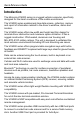


Table Of Contents
- Introduction
- About this Guide
- Model Configurations
- Features
- Unpacking
- Optional Accessories for VC6096
- Optional Accessories for VC6090
- Installing a SIM Card (VC6096 only)
- 1. Remove the T8 screw that secures the SIM Card Door and open the door.
- 2. Position the SIM Card with the contacts facing the back of the VC6096, and insert into the SIM Slot. The SIM Card corner notch fits into the slot only one way (See figure below).
- 3. Use a pen to push the SIM Card inwards to lock.
- 4. Place the SIM Card Door and secure the T8 Screw.
- 5. Torque the T8 Screw to 3.4 kgf-cm (3 in-lbs).
- Installing the SD Memory Card
- 1. Lift up the Protective Rubber Cap that covers the Memory Card Slot.
- 2. Position the SD Memory Card with the contacts facing the back of the VC6000 series and insert into the Memory Card Slot. The corner notch of the SD Memory Card fits into the Memory Card Slot only one way.
- 3. Use your pen to push the SD Memory Card inwards to lock.
- 4. Replace the Protective Rubber Cap to seal the Memory Card Slot.
- Mounting
- Free-standing Pedestal Mount
- Desk Mount
- Lift Trucks
- Guidelines for Routing Cables
- Mounting the VC6000 Series on Gas/Diesel-Powered Vehicles
- Connecting the Vehicle Power Cable
- 1. Disconnect the power terminals from the vehicle battery.
- 2. Connect the black wire to the vehicle’s negative power source.
- 3. Connect the green wire to the vehicle’s ignition switch.
- 4. Connect the red wire to the vehicle’s positive power source. Place a 10 A SLO BLO fuse inside the fuse holder, connected in-line with the Red Wire approximately 10 cm (4 inches) from the cable end.
- 5. Connect and turn clockwise to lock the Power Plug to Power Connector (PWR) of the VC6000 series (See Back Features on page 7). The length of the cable is 3 m (9.8 ft.).
- 6. When routing wires, slide Shrink Tubing over wires as required.
- 7. Connect the power terminals of the Vehicle Power Cable to the terminals of the vehicle battery.
- 8. Reconnect the vehicle battery.
- Connecting the Vehicle Power Cable
- Mounting the VC6090 on Electric-Powered Lift Trucks
- Access Requirements
- Important Mounting Information
- 1. Four stainless steel cap screws, 1/4”-20-X (M6x1.0-X) where X represents the length of the cap screws.
- 2. Four 1/4”-20 (M6x1.0) nyloc nuts
- 3. Four 1/4” (M6) flat washers
- 1. Disconnect the fork lift battery.
- 2. Connect the Power Converter to the vehicle battery as shown below:
- 3. Confirm the fuse is in the fuse mount: • For a 12V or 24V fork lift, use a 8A fast blow ceramic fuse. • For a 36V, 48V, or 60V fork lift, use a 5A fast blow ceramic fuse.
- 4. Route the cable from the power converter to the power source using the Cabling Installation Guidelines (see Guidelines for Routing Cables on page 14).
- 5. Connect the red wire to the electric lift truck's positive power source. Connect the black wire to the electric lift truck's negative power source.
- 6. Ensure the wiring connections created are sufficiently insulated from each other.
- 7. Reconnect the electric lift truck battery.
- Mounting the VC6000 Series on AC-powered Carts and Stationary Installation
- 1. Connect a ground wire between the VC6000 series and the facility ground system. The ground wire ring lugs should be connected to the Ground Point (GND) on the back of the VC6000 series using M4 screw.
- 2. Attach the 12 V DC cable of the Indoor Power Supply Unit to the Power Connector at the back of the VC6000 series and turn clockwise to lock. Rotate clockwise to lock the connector.
- 3. Connect the AC Cord into the Indoor Power Supply Unit.
- 4. Connect the plug of the AC Cord into a 100-240 V AC / 50-60 Hz Power Outlet.
- 5. If installed on an AC-powered Cart, secure the Indoor Power Supply Unit to the AC-powered Cart.
- Ground Polarity
- Connecting the Telemetry Cable (VC6096 only)
- Telemetry Cable
- 1. Plug the J1 connector into the Auxiliary port of the VC6000 series (See Back Features on page 7) and fasten the connection screws of the connector.
- 2. Plug connectors J2 and J3 to the telemetry receptacles of your vehicle data bus.
- 3. Connect the I/O Wires as required.
- Mounting the Combination Antenna (VC6096 only)
- 1. For best performance, it is recommended to install the antenna outside of the cabin. When installing the antenna in the vehicle cabin or indoors, keep a minimum distance of 70 cm (2.3 ft.) between the antenna and the VC6096.
- 2. The antenna should be directed vertically to the horizon to assure maximum exposure.
- 3. To ensure best performance, the antenna should be mounted as far away as possible from walls, floors and metal containing objects. Keep an obstacle free zone of 10 cm (3.9 inches) from walls, cabinets, air duct, metal-framed windows, doors etc.
- 4. When mounting the antenna inside the vehicle, it is recommended to install the antenna at the top right hand side of the windshield.
- Mounting the GPS Antenna (VC6096 only)
- 1. Recommended GPS antenna - Motorola part number 8508851K59.
- 2. The GPS antenna must be mounted on the top of the dashboard or vehicle roof. For best performance, install the GPS antenna on the center-line of the vehicle roof.
- 3. Keep a minimum distance of 40 cm (16 inches) between the Combination antenna and the GPS antenna.
- 4. The antenna is attached by a magnet to a flat metal surface (minimum 7 cm x 7 cm, 2.75 inches x 2.75 inches). Before mounting the GPS antenna on a dashboard, install a flat Metal Plate on the dashboard to hold the GPS antenna.
- 5. The antenna should be directed parallel to the horizon to assure exposure to as many satellites as possible.
- 6. If possible, the antenna location must not be obstructed by any structure or object. When mounting the antenna on a roof ensure at least 7.6 cm (3 inches) of clear space around it.
- Operating the VC6000 series
- Troubleshooting
- Regulatory Information
- Country Approvals
- Health and Safety Recommendations
- 1. Get to know your wireless device and any features such as speed dial and redial. If available, these features help you to place your call without taking your attention off the road.
- 2. When available, use a hands free device.
- 3. Let the person you are speaking with know you are driving; if necessary, suspend the call in heavy traffic or hazardous weather conditions. Rain, sleet, snow, ice, and even heavy traffic can be hazardous.
- 4. Dial sensibly and assess the traffic; if possible, place calls when you are not moving or before pulling into traffic. Try to plan calls when your car will be stationary. If you need to make a call while moving, dial only a few numbers, check the ...
- 5. Do not engage in stressful or emotional conversations that may be distracting. Make people you are talking with aware you are driving and suspend conversations that have the potential to divert your attention from the road.
- 6. Use your wireless phone to call for help. Dial the Emergency services, (9-1-1 in the US, and 1-1-2 in Europe) or other local emergency number in the case of fire, traffic accident or medical emergencies. Remember, it is a free call on your wireles...
- 7. Use your wireless phone to help others in emergencies. If you see an auto accident, crime in progress or other serious emergency where lives are in danger, call the Emergency Services, (9-1-1 in the US, and 1-1-2 in Europe) or other local emergenc...
- 8. Call roadside assistance or a special non-emergency wireless assistance number when necessary. If you see a broken-down vehicle posing no serious hazard, a broken traffic signal, a minor traffic accident where no one appears injured, or a vehicle ...
- FCC / EU RF Exposure Guidelines
- Indoor Power Supply
- Wireless Devices - Countries
- Radio Frequency Interference Requirements
- Radio Frequency Interference Requirements - Canada
- Marking and European Economic Area (EEA)
- Waste Electrical and Electronic Equipment (WEEE)

6 VC6000 Series Vehicle Computers
Features
Front Features
1
See “System Indication LED” on page 25.
2
For LED indications, refer to your enterprise application guide.
3
VC6090 numeric keys also marked as F1-F20 function keys (with Ctrl / Alt keys)
4
For key function, refer to the text displayed on the screen.
5
Model VC60x0-Home key. Model VC6096-Call key (For Home, press Fn+H keys).
6
Model VC60x0-Back key. Model VC6096-End key (For Back, press Fn+J keys).
7
For keys operation, refer to your enterprise application guide.
1. Power Button with System Indication LED
1
2. Two green LEDs driven by application
2
3. Volume up/down key (6 levels)
4. Brightness up/down key
5. Microphone
6. Full QWERTY keypad
3
7. Left soft key
4
8. Right soft key
4
9. Call or Home key
5
10. End or Back key
6
11. Navigation key
12. Select key
13. Speaker
(embedded)
14. Function keys
7
15. Touch screen
2
4
8
9
6
7
3
11
12
13
5
10
14
15
1