
User's Manual
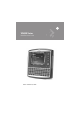

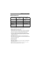


Table Of Contents
- Introduction
- Model Configurations
- Warranty
- Patents
- Features
- Front Features
- Back Features
- Installing a SIM Card (VC6096 only)
- 1. Remove the T8 screw that secures the SIM card door and open the door.
- 2. Position the SIM Card with the contacts facing the back of the VC6000 series, and insert into the SIM Slot. The SIM Card corner notch fits into the slot only one way (See figure below).
- 3. Use a pen to push the SIM Card inwards to lock.
- 4. Place the SIM Card Door and secure the T8 screw.
- 5. Torque the screw to 3.4 kgf-cm (3 in-lbs).
- Installing an SD Memory Card
- 1. Lift up the protective rubber cap that covers the Memory Card Slot.
- 2. Position the SD Memory Card with the contacts facing the back of the VC6000 series and insert into the Memory Card Slot. The corner notch of the SD Memory Card fits into the Memory Card Slot only one way.
- 3. Use your pen to push the SD Memory Card inwards to lock.
- 4. Replace the Protective Rubber Cap to seal the Memory Card Slot.
- Mounting the VC6000 series
- Guidelines for Routing Cables
- Connecting the Vehicle Power Cable
- 1. Disconnect the power terminals from the vehicle battery.
- 2. Connect the black wire to the vehicle’s negative power source.
- 3. Connect the green wire to the vehicle’s ignition switch.
- 4. Connect the red wire to the vehicle’s positive power source. Place a 10 A SLO BLO fuse inside the fuse holder, connected in-line with the Red Wire approximately 4” from the cable end, as shown below.
- 5. Connect and turn clockwise to lock the Power Plug to Power Connector (PWR) of the VC6000 series (see Back Features on page 4). The length of the cable is 9.8 ft (3 m).
- 6. When routing wires, slide Shrink Tubing over wires as required.
- 7. Connect the power terminals of the Vehicle Power Cable to the terminals of the vehicle battery.
- Cigarette Lighter Cable
- Connecting the Telemetry Cable
- Mounting the Combination Antenna (VC6096 only)
- 1. For best performance, it is recommended to install the antenna outside of the cabin. When installing the antenna in the vehicle cabin or indoors, keep a minimum distance of 70 cm (2.3 ft) between the antenna and the VC6000 series.
- 2. The antenna should be directed vertically to the horizon to assure maximum exposure.
- 3. To ensure best performance, the antenna should be mounted as far away as possible from walls, floors and metal containing objects. Keep an obstacle free zone of 10 cm (3.9 inches) from walls, cabinets, air duct, metal-framed windows, doors etc.
- 4. When mounting the antenna inside the vehicle, it is recommended to install the antenna at the top right hand side of the windshield.
- Mounting the GPS Antenna (VC6096 only)
- 1. Recommended GPS antenna - Motorola part number 8508851K59.
- 2. The GPS antenna must be mounted on the top of the dashboard or vehicle roof. For best performance, install the GPS antenna on the center-line of the vehicle roof.
- 3. Keep a minimum distance of 40 cm (16 inches) between the Combination antenna and the GPS antenna.
- 4. The antenna is attached by a magnet to a flat metal surface (minimum 2.75 inches x 2.75 inches, 7 cm x 7 cm). Before mounting the GPS antenna on a dashboard, install a flat Metal Plate on the dashboard to hold the GPS antenna.
- 5. The antenna should be directed parallel to the horizon to assure exposure to as many satellites as possible.
- 6. If possible, the antenna location must not be obstructed by any structure or object. When mounting the antenna on a roof ensure at least 3” of clear space around it.
- Connecting the VC6000 Series Indoor
- 1. Connect a ground wire between the VC6000 series and the facility ground system. The ground wire ring lugs should be connected to the Ground Point (GND) at the back of the VC6000 series using M4 screw.
- 2. Mount the Combination Antenna outdoor. Contact the mast of the antenna, by a metal bonding, to a ground wire that runs direct...
- 3. Connect the WWAN plug of the Combination Antenna cable to the WWAN antenna connector at the back of the VC6000 series (VC6096 only).
- 4. Connect the WLAN plug of the Combination Antenna cable to the WLAN antenna connector at the back of the VC6000 series (VC6096 only).
- 5. Attach the 12 V DC cable of the Indoor Power Supply Unit to the Power Connector at the back of the VC6000 series and turn clockwise to lock.
- 6. Connect the AC Cord into the Indoor Power Supply Unit.
- 7. Connect the AC Cord plug into a 100-240 V AC / 50-60 Hz Power Outlet.
- Optional Mounting
- System Indication LED
- Controlling Screen Brightness
- Controlling Keypad Illumination
- 1. Press the Ctrl key to lock in down position.
- 2. Press the Brightness up/down key to increase/decrease the keypad illumination. The VC6000 series automatically returns to normal operation after six seconds if the up/down key is not pressed.
- 3. Press the Ctrl key to unlock in up position.
- In Standby mode, the screen display and backlight illumination automatically turn off after a period of two minutes when VC6000 series is not active.
- Resume from Standby Mode
- Resetting the VC6000 series
- Function Keys
- Troubleshooting
- Regulatory Information
- Country Approvals
- Health and Safety Recommendations
- 1. Get to know your wireless device and any features such as speed dial and redial. If available, these features help you to place your call without taking your attention off the road.
- 2. When available, use a hands free device.
- 3. Let the person you are speaking with know you are driving; if necessary, suspend the call in heavy traffic or hazardous weather conditions. Rain, sleet, snow, ice, and even heavy traffic can be hazardous.
- 4. Dial sensibly and assess the traffic; if possible, place calls when you are not moving or before pulling into traffic. Try to...
- 5. Do not engage in stressful or emotional conversations that may be distracting. Make people you are talking with aware you are driving and suspend conversations that have the potential to divert your attention from the road.
- 6. Use your wireless phone to call for help. Dial the Emergency services, (9-1-1 in the US, and 1-1-2 in Europe) or other local ...
- 7. Use your wireless phone to help others in emergencies. If you see an auto accident, crime in progress or other serious emerge...
- 8. Call roadside assistance or a special non-emergency wireless assistance number when necessary. If you see a broken-down vehic...
- FCC / EU RF Exposure Guidelines
- Indoor Power Supply
- Wireless Devices - Countries
- Radio Frequency Interference Requirements
- Radio Frequency Interference Requirements - Canada
- Marking and European Economic Area (EEA)
- Waste Electrical and Electronic Equipment (WEEE)

Quick Reference Guide 5
Unpacking
The following items are contained inside the shipping box:
• VC6000 series
• Hardware Kit (including five M4 installation screws)
•This guide
Optional Accessories
3
NOTE A hardware kit that contains optional accessories is
provided separately inside the shipping box.
Part Number Description
FLN4048 Combination Antenna
8508851K59 External GPS Antenna
0102246H51 Indoor Power Supply
50-16000-2212 AC Cord (USA)
3087568V83 VC6096 WWAN RF Cable (3m, 9.8ft.)
3087568V84 VC6096 WLAN RF Cable (3m, 9.8ft.)
3071815Y17
VC6096 Cigarette Lighter Cable (CLA) Power Supply
Cable
3071815Y13 VC6096 Vehicle Power Cable
3071815Y15 9-Pin Deutsch Cable
3071815Y23 9-Pin Deutsch Cable (J1939 protocol)
3071815Y24 9-Pin Deutsch Cable (J1708 protocol)
3071815Y14 6-Pin Deutsch Cable
3089906V60 50 Pin Cable
3089906V63 9-Pin Deutsch Telemetry Cable
3089906V61 6-Pin Deutsch Telemetry Cable
3071815Y25 9-Pin Deutsch Telemetry Cable (J1708 protocol)
3071815Y26 9-Pin Deutsch Telemetry Cable (J1939 protocol)