Zebra® TTP 7030™ Kiosk Receipt Printer Technical Manual P1003636-002
© 2009 ZIH Corp. The copyrights in this manual and the software and/or firmware in the TTP 7030 described therein are owned by ZIH Corp. and Zebra’s licensors. Unauthorized reproduction of this manual or the software and/or firmware in the TTP 7030 may result in imprisonment of up to one year and fines of up to $10,000 (17 U.S.C.506). Copyright violators may be subject to civil liability.
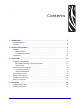
Contents 1 • Introduction . . . . . . . . . . . . . . . . . . . . . . . . . . . . . . . . . . . . . . . . . . . . . . . . . . . . 7 About This Manual . . . . . . . . . . . . . . . . . . . . . . . . . . . . . . . . . . . . . . . . . . . . . . . . . . . . . . . 7 Contacts . . . . . . . . . . . . . . . . . . . . . . . . . . . . . . . . . . . . . . . . . . . . . . . . . . . . . . . . . . . . . . . 8 2 • Product Presentation . . . . . . . . . . . . . . . . . . . . . . . . . . . . . . . . . . . . . . . . . . .
5 • Programming . . . . . . . . . . . . . . . . . . . . . . . . . . . . . . . . . . . . . . . . . . . . . . . . . . 27 How The Commands Are Described . . . . . . . . . . . . . . . . . . . . . . . . . . . . . . . . . . . . . . . . Mnemonic . . . . . . . . . . . . . . . . . . . . . . . . . . . . . . . . . . . . . . . . . . . . . . . . . . . . . . . . . Hex . . . . . . . . . . . . . . . . . . . . . . . . . . . . . . . . . . . . . . . . . . . . . . . . . . . . . . . . . . . . . . Decimal . . . . . . . . . .
8 • Interface . . . . . . . . . . . . . . . . . . . . . . . . . . . . . . . . . . . . . . . . . . . . . . . . . . . . . . 95 USB Interface . . . . . . . . . . . . . . . . . . . . . . . . . . . . . . . . . . . . . . . . . . . . . . . . . . . . . . . . . . 96 Serial Option, TTP 7030 . . . . . . . . . . . . . . . . . . . . . . . . . . . . . . . . . . . . . . . . . . . . . . . . . 97 Setup Options . . . . . . . . . . . . . . . . . . . . . . . . . . . . . . . . . . . . . . . . . . . . . . . . . . . . . .
Notes • ___________________________________________________________________ __________________________________________________________________________ __________________________________________________________________________ __________________________________________________________________________ __________________________________________________________________________ __________________________________________________________________________ _____________________________________________
1 Introduction About This Manual This manual contains the information required to install the TTP7030 printer and to run it from a host computer such as a PC. Programming on page 27 gives the applicable control codes and escape sequences supported by the printer processor firmware. Other chapters of the manual contain information about the printer error codes, communications-parameters, test print functions, specifications, replacement parts, etc.
About This Document Contacts Contacts Technical Support via the Internet is available 24 hours per day, 365 days per year. Web Site: www.zebra.com E-mail Back Technical Library: E-mail address: emb@zebra.com Subject line: Emaillist Self Service Knowledge Base: www.zebra.com/knowledgebase Online Case Registration: www.zebra.
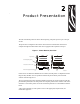
2 Product Presentation The TTP 7030 kiosk printer uses direct thermal printing. The print speed is up to 75 mm per second. The printer has an integrated control board. The TTP 7030 communicates with the host computer through the USB interface and can be equipped with an optional serial port.
Product Presentation Figure 2 • Printer Exterior, Side View Status indicator Feed-forward button Paper entry Print mechanism flip-back handle Paper release lever Printhead lifted Paper released Normal operation Paper exit FRONT Control board SW98049 P1003636-002 TTP 7030™ Technical Manual 10/05/2009
Product Presentation Indicators Indicators Status Indicator The status indicator (see Figure 1, Printer Exterior, Rear View , on page 9) has several functions: ON constantly Indicates that the printer is operational. Flashes, pauses, flashes Indicates warnings of non-severe error. The number of flashes reflects the warning-code: • 2 flashes: Paper low Note • This signaling is disabled by default. It can be disabled/enabled by setting parameter P52.
Product Presentation Feed Button Feed Button The Feed button will feed, cut, and present a complete page. Any data in the print buffer will be printed. If the buffer is empty the page will be blank. In black mark mode, the page will be synchronized with the black mark. Press and hold the Feed button while turning on the power, or while opening and closing the printhead to print a self-test printout. See Making a test printout on page 14.
3 Installation 10/05/2009 TTP 7030™ Technical Manual P1003636-002
Installation Installation Considerations Installation Considerations The TTP 7030 printer is designed to be installed in an enclosure such as a self-service kiosk. The illustration below gives an example of a printer-mounting shelf. See also Printer dimensions on page 110. 3D solid models and outline drawings for CAD are available in the partner section of www.zebra.com. Figure 3 • Example of a Simple Shelf for Fastening a Standard Printer 12.0 Top view 104.0 76.0 84.5 (116.5) 19.0 26.0 1.5 128.
Installation Installation Considerations Electrostatic Discharges, and Earth Currents Preventing ESD and earth currents from affecting the printer operation requires proper connection of the printer chassis to protective earth through a mounting platform or through a separate earth conductor. Ambient Light There is an optical sensor just inside the paper exit at the front of the printer.
Installation Connecting To The Computer Connecting To The Computer Caution • Using a non-Zebra power supply may cause excessive EMC interferences and void the EMC certifications of the printer. Connect the TTP 7030 1. Connect J13 of the printer to the USB port of the computer or the USB hub to be used. USB connectors can be recognized by the following symbol: . Note • Connector J13 is a 4-pin USB type B connector. See USB, TTP 7030 on page 877 for pin assignment.
Installation Connecting To The Computer Figure 5 • Fitting a serial adapter to the printer.
Installation Connecting the Power Connecting the Power Using the Zebra power supply (see Ordering Numbers on page 127 for ordering number): 1. Make sure the line voltage selector on the power supply is set to your local line voltage (only PSU 01035-014). 2. Connect the cable from the power supply to J8. 3. Connect the power cable to the line outlet. 4. Apply power to the printer. If you use another type of power supply unit, connect the voltages as shown in Figure 6.
Installation Making A Test Printout Making A Test Printout 1. Is a power button available for the printer? If… Then… Yes a. Remove power from the printer. b. Hold the feed-forward button depressed while powering ON the printer. c. Keep the button depressed until printing starts. This produces a printout showing the firmware program version and date, control board revision number and serial number, name of loaded fonts and logotypes, and the parameter settings. d.
Installation Installing A Printer Driver Installing A Printer Driver Printer drivers for most versions of Microsoft Windows™, are available on the Zebra web site http://www.zebra.com. See Part Number List on page 115 for the part number. Please follow the installation instructions that accompany the drivers and refer to the Kiosk Driver Reference Guide, Part Number P1006873-001, available on www.zebra.com for detailed driver information.
Installation Paper Level Sensors Paper Level Sensors The printer has inputs for one paper-near-end sensor, and one weekend sensor. Figure 7 • Paper Level Sensor Indicators on Roll Holder Optical weekend sensor. Adjustment range equals approximately 30 to 150 m of paper Lock screw GND OUT 20-60 mm +5V SENSOR +5V SENSOR GND OUT Optical paper-near-end sensor. Activated when a couple of meters of paper remain. 25.
Installation Paper Level Sensors Figure 8 • Paper-near-end Sensor Connection Inside printer Near end Roll holder shaft Gray 2 Blue 3 Green 4 Gray 5 Blue 6 Green 47 k J1 1 200 Weekend sensor Sharp GP2S40 lex 0 Mo 5-060 02 43 47 k 2 1 4 6 3 5 +5 V 200 lex Mo 08 0-0 03 43 Sharp GP2S40 22 WE SENSE PL SENSE Paper-nearend sensor Sensor levels: <0.
4 Operation 10/05/2009 TTP 7030™ Technical Manual P1003636-002
Operation Installing a Paper Roll Installing a Paper Roll 1. Turn the new paper roll as shown. The paper should be inserted into the printer with the temperature-sensitive side up. Figure 9 • Paper Roll Orientation 2. Tear off a full turn of the paper (approximately 0.5 m) from the new paper roll. Caution • This is important since the outer end of the paper is usually fixed to the roll with some type of glue or self-adhesive substance that might otherwise cause paper jam or even print head damage.
Operation Installing a Paper Roll 4. Cut the paper in a suitable angle. See Figure 11. Figure 11 • Suitable paper edge for auto load 70º Thermal side (top) Cut off at a 70º-90º angle 90º Thermal side (top) Note • The paper sensor is on the same side as the blue paper release lever (where the arrow points in Figure 12, Insert the New Paper, on page 25). If the paper is cut in a direction opposite to that as shown in the figure above, the sensor will not detect the paper. 5.
Operation Clearing Paper Jams Clearing Paper Jams Should a paper jam occur, follow the procedure below: 1. Tear off the paper close to the paper roll and open the print module. Figure 13 • Open the Print Module 2. Lift the print head by pushing the paper release lever upwards. 3. Remove all jammed paper by gently pulling the paper up and out of the print module. Make sure the paper path is clear and then close the printhead. Caution • NEVER pull paper backwards through the print mechanism.
5 Programming There are two completely different ways of setting up the printout: Text oriented and driver oriented style. 10/05/2009 Command Code The printout can be seen as the page of a simple word processor. You send text and graphics to the printer, which prints the information in the same sequence as the data is received. Design features are limited to the font stored in the flash PROM of the printer. It is possible to select a fixed page length.
Programming Figure 15 • Ticket Styles Driver (Windows) receipt Text receipt text text text text text text text text 1 234567 890128 Text text text text text text text text text text text text text text text text text text text text text text text text text text text text text text text text text Text text 1 234567 890128 Bar codes can be added. Text can be printed in any orientation, font, and size. Lines can be added.
Programming How The Commands Are Described How The Commands Are Described Purpose of command Mnemonic ESC ! n1 1B 21 n1 27 33 n1 Hex Dec Select font Decimal representation of command Hex representation of command SW 03002 Mnemonic Is the popular command name that should be easy to remember. Hex Give the command in hex representation Decimal Give the command in decimal representation Values n1, n2, etc. represents values that you set with the commands.
Programming How The Commands Are Described Two-Byte Character Definitions Some commands and parameters are used with a two-byte value definition because the internal structure of the printer's firmware limits access to values greater than 255. To represent values greater than 255 in this two-byte format, divide the value by 256. The whole number (quotient) is the value of the leading byte and the remainder (modulo) is the value of the trailing byte.
Programming Summary Of Control Codes & Escape Sequences Summary Of Control Codes & Escape Sequences Table 2 • Control Codes and Escape Sequences in Alphabetical Order Command Hex Decimal Function Page BS 08 8 Backspace page 38 CAN 18 24 Cancel page 38 CR 0D 13 Carriage return page 38 EM 19 n1 25 n1 Enforced Clear Presenter page 51 ENQ 05 5 Clear Presenter page 52 ESC ACK n1 1B 06 n1 27 6 n1 Acknowledge Marker page 63 ESC ! n1 1B 21 n1 27 33 n1 Select Font page 35 ESC
Programming Summary Of Control Codes & Escape Sequences Table 2 • Control Codes and Escape Sequences in Alphabetical Order Command Hex Decimal Function Page ESC ENQ 11 1B 05 0B 27 5 11 Head temperature Enquiry page 61 ESC ENQ 12 1B 05 0C 27 5 12 Bootware version Enquiry page 61 ESC ENQ c 1B 05 63 27 5 99 Device ID Enquiry page 62 ESC ENQ P n1 1B 05 50 n1 27 5 80 n1 Parameter-setting data Enquiry page 62 ESC FF n1 1B 0C n1 27 12 n1 Eject (run presenter) page 51 ESC g n1...
Programming Software Command Syntax Software Command Syntax The commands in this section are grouped after what they do, and these groups are sorted in a theoretical usage sequence. It starts with commands for specifying the printed page — through text-and-graphics commands — to cut-and-present commands. System and status commands are presented at the end. Page Setup Page setup is performed with parameters instead of dedicated commands.
Programming Text Commands Text Commands Text received by the printer is printed with the currently selected font and font attributes. Text exceeding the page width is wrapped with the line spacing selected. ESC o n1 1B 6F n1 27 111 n1 Text and Logotype Orientation hex decimal Changes the orientation of text and logotypes. n=0 Gives portrait orientation n=1 Gives landscape orientation Portrait and landscape can be mixed on the same printout.
Programming Text Commands ESC ! n1 1B 21 n1 27 33 n1 Select Font hex decimal This command selects one of eight fonts. The font design depends on which fonts have been loaded1 into the printer. Make a test printout to see which fonts are available in your printer.
Programming Text Commands ESC T n1 1B 54 n1 27 84 n1 Reversed/Inversed Text Hex decimal Selects normal or reversed print. n=0 Gives normal print, black on white n=1 Gives reversed print, white on black Single words, characters, or complete text lines can be reversed. Note • Reverse text and underline swaps the background with the foreground. This means that the order in which the commands are issued affect the printout if one text overlaps another.
Programming Text Commands ESC w n1 1B 77 n1 27 119 n1 Text Width hex decimal Applicable n values are 0 — 7. n=1 Increases the character width to 2 times the basic character width. n=2 Increases the character width to 3 times the basic character width etc. n=0 Resets the character width to the basic character width. In combination with variable character height h, give highly legible characters depending on the font to which the command has been applied.
Programming Text Commands BS 08 Hex 8 Decimal Backspace Moves the print-position one step to the left. Backspace can be used to combine characters. For instance to print a Ø, send text commands O BS / to the printer, and the slash will overprint the O. Only one backspace can be used at a time. Excessive backspaces will be ignored. CAN 18 Cancel hex Cancels text and attributes sent before the command on the same line. Commands, are not cancelled.
Programming Text Commands ESC d n1 1B 64 n1 27 100 n1 hex decimal Make n Linefeeds Executes the number of linefeeds as defined by variable n1. The length of each line feed is determined by the default value for selected font (see parameter 13 on page 77). The print position is returned to the beginning of the line. Any text on the line is lost. To avoid losing text, send an before sending d.
Programming Barcode Commands Barcode Commands TTP 7030 can print EAN 8, EAN 13, EAN128, UPC, 2-of-5 Interleaved, ISBN, Code39 and Code128 barcodes with it’s standard firmware. A special firmware is available where the barcodes are replaced with the PDF 417 2D barcode. See Firmware on page 104, and PDF417 command. Example • The example below will print an EAN barcode with height = 10 mm, 15 mm in from the right margin.
Programming Barcode Commands Figure 16 • Samples of barcodes . Selecting code 128 and starting the data string with FNC1 generates an EAN128 code.
Programming Barcode Commands ESC B S n1...n11 1B 42 53 n1...n11 27 66 83 n1...n11 Barcode Field Specify hex decimal Bar codes can only be printed in portrait mode unless Fixed Document Mode is selected with parameter n36. The command reserves an information field as a bar code field. The command also identifies the type, number of digits, and the configuration of bars to be placed in the bar code field. P1003636-002 n1 Specifies the bar code field No. (0—15).
Programming Barcode Commands ESC BW n1 nx 1B 027 42 57 066 087 n1 n1 nx nx Barcode Write Hex Decimal Writes data to the bar code field reserved by the BS command. n1 Specifies the field No. Range 0 to 15. Fields can be specified in any order but other values than 0 to 15 are ignored. n2 . . . nx Specifies bar code data bytes. To create a bar code add-on, insert a space character and then the data for the add-on. Two of five characters are allowed of the add-on.
Programming Barcode Commands ESC 1B 027 | n1 nx 7C 124 n1 n1 nx nx Barcode Print (PDF 417)* Hex Decimal *. PDF 417 requires special firmware in the printer. See “Firmware” on page This command positions and prints a PDF 417 2D barcode. "|" n1 Specifies the type of bar code.
Programming Graphics Commands Graphics Commands In 80 mm printers, the line length is 72 bytes and in 112 mm printers it is 104 bytes. ESC b n1...n5 data 1B 62 n1...n5 27 98 n1...n5 Data Data Print Bitmap at XY-position hex decimal Prints a black & white Windows bitmap (BMP-file) at the specified X-Y position. The bit-map must be a complete uncompressed Windows bitmap where the data starts with BM. Max size is limited to the free RAM printed on the self-test printout. .
Programming Graphics Commands ESC r n1...n9 1B 72 n1...n9 27 114 n1...n9 Print Ruler Line hex decimal Prints a ruler line across the paper. A ruler line is normally used to divide the printout into logical parts to make it easier to read. A ruler line is actually an area defined by a start X-Y position and a stop X-Y position. This area is filled with black or a checkered pattern.
Programming Graphics Commands ESC g n1...n5 1B 67 n1...n5 27 103 n1...n5 Print Logotype hex decimal Prints a customized logotype2 stored in the flash PROM. See also Logotypes on page 66. n1 One-byte logotype identification No. (0—15) n2n3 Two-byte definition of desired print position in X-direction measured from left-hand edge of the page (see Printable Area on page 86 regarding definition of “page”). X-direction is perpendicular to the paper transport direction.
Programming Print Commands Print Commands ESC p 1B 70 27 112 Print Hex Decimal This command makes the printer print the contents of the line buffer. Text is converted from text to pixel lines and stored in the line buffer when an LF is received. If the line buffer is empty when p is received, nothing is printed. Text to be printed p prints "Text to be printed" on the paper.
Programming Print Commands ESC j n1 1B 6A n1 27 106 n1 hex decimal Paper Reverse The value n represents the number of dot lines the paper is to be transported backwards. Range: 1–255. Caution • Paper reverse may cause problems when used at the top of the page. Doing so may cause paper jam when feeding forward again. The printer may also lose grip of the paper. NEVER reverse more than 10 mm at top of page! A dot line is 0.125 mm, and 255 dot lines equal approximately 32 mm.
Programming Cut And Present Commands Cut And Present Commands RS 1E 30 Cut and Eject Hex Decimal Effects a paper cut-off and an eject through the presenter module. The RS command automatically gives the eject length of 50 mm in addition to the factor stored in parameter p47. If the printout length is too short, paper-feed is added until the minimum printout length (set by parameters 37 and 38) is reached, before execution of the Cut command. Note • The cut position is 17 mm before the print line.
Programming Cut And Present Commands ESC FF n1 1B 0C n1 27 12 n1 Eject (run presenter) hex decimal ejects the document through the presenter module. Variable n represents the number of eject-steps. One step is approximately 2 mm The maximum number of steps is 255 Normally, this command is placed after a cut command () to partially eject the printout to the customer.
Programming Cut And Present Commands ENQ 05 5 Hex Decimal Clear Presenter Clear the paper-path in the presenter form printouts. For example, to eject a document not removed during the previous print/cut/eject operation. Parameter No. 45 controls how the presenter is cleared.
Programming System Related Commands System Related Commands ESC ? 1B 3F 27 63 Reset (full) Hex Decimal Restarts the printer with a complete reset. This is the same as power off/on. ESC @ 1B 40 27 64 Reset (initialize) Hex Decimal Terminates the processing and initializes the control board. The control board is reset to default-values (same as after power ON). Do not use this command as part of a print data command string.
Programming System Related Commands ESC & 0 1B 26 00 27 38 0 Load Font hex decimal This command is used to load a font to the printer flash PROM. The font is placed in the first free address position in the order of load sequence. A Zebra font-file consists of a header containing data describing the font as well as data for each individual character in the font. Fonts can be designed with the font editor and loaded or deleted with the software available for free on the Zebra web site.
Programming System Related Commands ESC & P n1...n2 1B 26 50 n1...n2 27 38 80 n1...n2 Set Parameter Value hex decimal A number of bytes in the flash PROM hold various parameter values called default parameters. One or several of them can be overridden temporarily with this command. n1 Parameter number, range 1 -255. n2 Parameter value. See Default Parameter Settings on page 69. The permanently stored parameters will be used again after a printer-reset command or at power ON.
Programming Status Reporting Commands Status Reporting Commands See also Status Reporting on page 68. Note • All status commands are immediate, that is they pass the print queue and is answered directly. ESC ENQ 1 1B 05 01 27 5 1 Status Enquiry hex decimal A status enquiry results in response ACK (06h) if all sensors are clear, but NAK (15h) + code if one or more sensors report fault condition.
Programming Status Reporting Commands Note • Errors 02, 05 and FF are terminal faults that require you to reset the printer before it will be operable again. The printer automatically recovers from the other error conditions as soon as the error is corrected. A status enquiry command can only return one status code at a time.
Programming Status Reporting Commands ESC ENQ 004 1B 05 04 27 5 4 Fonts and Logotype Enquiry hex decimal Requests multiple bytes of information regarding loaded fonts and logotypes.
Programming Status Reporting Commands ESC ENQ 6 1B 05 06 27 5 6 Status Report hex decimal Results in a 2-byte response, reflecting the status of each sensor. This command is intended as a go/no go indication. When everything is OK, this status report returns 0. Note • If no weekend sensor is installed, 64 is returned when everything is OK. If no weekend or paper-near-end sensors are installed, 64+2=66 is returned when OK.
Programming Status Reporting Commands ESC ENQ 7 1B 05 07 27 5 7 Firmware-version Enquiry Hex decimal Results in a 2-byte response representing the version of the installed firmware. The first byte represents major versions, and the second byte minor versions. If no firmware is loaded, the printer will answer with 00h. Example • Send<7> Read <2><29> That is, a response with the value <1><29> indicates version 2.41.
Programming Status Reporting Commands ESC ENQ 11 1B 05 0B 27 5 11 Head Temperature Enquiry hex decimal Results in a 1-byte response representing the temperature of the Printhead. Example • Send<11> Readn Where n is a value representing the approximate temperature in Celsius. ESC ENQ 12 1B 05 0C 27 5 12 Bootware Version Enquiry hex decimal Results in a 2-byte response representing the version of the installed bootware.
Programming Status Reporting Commands ESC ENQ c 1B 05 63 27 5 99 Device ID Enquiry hex decimal Results in a string containing the device ID in the Windows Plug and Play string format. The two first bytes represent the string length.
Programming Status Reporting Commands ESC ACK n1 1B 06 n1 27 6 n1 Acknowledge Marker hex decimal n1 One-byte marker. Range 1h to 255h The "acknowledge marker" n is placed in the command queue and when the execution of commands reaches the marker it is sent back to the host computer. This is an addition to the status commands that pass the queue and are answered immediately when received.
Programming Font Loading Font Loading The printer can store 8 fonts in its flash PROM. The memory available for fonts is printed on the self-test printout. The character size is fixed3, so you must load one font file for each character size you require. The fonts are given font numbers when they are loaded into the printer. The first font is assigned number 0 and the next font 1 etc. up to font 7.
Programming Font Loading Char_bitmap data: Bitmap data for all characters that are to be defined. Char_width Char_sizeY Baseline A Char_width Char_Ystart Char_Yheight Char_width Char_width A Wg Char_pitch Char_sizeX Char_pitch Char_pitch Character bitmap data: A character is made up of a bitmap the size of which is: Char. width (X) * Char. Height (Y) bytes.
Programming Logotypes Logotypes Up to 16 logotypes can be stored in the flash PROM of the printer. The logotypes can be positioned and printed out with commands g or L. The exact number of logotypes and their sizes is determined by the total amount of memory used for fonts, logotypes and loaded firmware. Make a test printout to see how much memory is available.
Programming Logotypes Printing To print a logotype you can use two commands, L, prints the logotype at the current cursor position, just like any character. g prints the logotype at a specified X-Y position. n1 One byte logotype number, (0—15) n2n3 Two byte X position measured in pixels from the left hand edge of the print window. n4n5 Two byte Y position in pixels from top of the page.
Programming Status Reporting Status Reporting The printer is equipped with a number of sensors that report the printer status and various error conditions such as out-of-paper, previous printout not removed, etc. A good practice in unattended printer applications is to check for errors and paper availability before printing. 1. Send a Status Report Query (<6>, see page 59) and check that the answer is "No errors" 2.
Programming Default Parameter Settings Default Parameter Settings Some of the printer settings can be stored in the flash PROM so that they will be used also after power OFF. The stored parameter settings are printed out on the self-test printout. The number in front of the function is the parameter number (n) used when setting the parameter with the command &P. You can use the parameter settings pretty much like normal commands.
Programming Default Parameter Settings Notes • ___________________________________________________________________ __________________________________________________________________________ __________________________________________________________________________ __________________________________________________________________________ __________________________________________________________________________ __________________________________________________________________________ ____
6 Default Parameter Settings Parameter number Default value 0 Default 0 Min 255 Max 47 Description as printed on self test printout DRV indicates that the Windows driver overrides setting Eject calibration constant (mm) Range DRV SW 02001 Default Value The default values indicated are "factory default settings" you get by sending &. These are not necessarily the settings that your printer was originally delivered with because many printers have customized settings when delivered.
Default Parameter Settings Summary Of Parameter Settings Summary Of Parameter Settings Parameter Description ESC&F <010> Default Page 1 Baud rate 96 (9600 Baud) page 73 2 Data bits 8 page 73 3 Parity 0 (No parity) page 73 4 Flow control 2 (Hardware) page 74 5 Disable parallel port signaling 0 (No) page 75 7 Burn time 5 page 76 8 Print speed 17 (75 mm/s) page 76 9 Presenter loop length 10 (32 cm) page 76 10 Pulse control 1 (1 burn pulse) page 77 12 Font attribute
Default Parameter Settings Serial Interface Set-Up Serial Interface Set-Up 1 96 24 11 Default Min Max Baud Rate Note • The new value is not valid until the parameters are stored and the printer restarted. Sets the communication speed on the serial interface.
Default Parameter Settings Serial Interface Set-Up 4 2 Default 0 Min 2 Max Flow-control1 Select what handshaking to use on the serial interface. &P<4><0> No flow control &P<4><1> Xon / Xoff * &P<4><2> Hardware *. DO NOT USE if you send any type of binary data like graphics data, status requests etc. Xon / Xoff only works when plain text is sent unidirectional to the printer.
Default Parameter Settings Parallel Port Setup Parallel Port Setup 5 0 Default 0 Min 1 Max Disable Parallel Port Signaling Pins 12 and 15 on the parallel port signals paper out and error. However, in an unattended kiosk you may not want this because it causes the host computer to stop communicating, and the operating system may display a banner on the kiosk screen.
Default Parameter Settings Print Setup Print Setup 7 5 Default 1 Min 15 Max Burn Time DRV Note • DRV indicates that, when using Windows, the driver takes over this setting so please set appropriate value in the driver properties/document defaults. A long burn time gives darker print. On insensitive paper types you may have to increase the burn time to get an acceptable print quality.
Default Parameter Settings Print Setup 10 1 Default 0 Min 3 Max Print Head Pulse Control Controls what the printer does with buffered data: &P<10><0> 1 burn pulse + history &P<10><1> 1 burn pulse &P<10><2> 2 burn pulses + history &P<10><3> 2 burn pulses Adding history pulse enhances print quality. Dividing burning into two burn pulses reduces the peak current consumption. 13 0 Default 0 Min 30 Max Line Spacing The line spacing is normally set by the font height.
Default Parameter Settings Print Setup 33 *. 0 Default 0 Min 4 Max CR/LF Behavior* v=0 is suitable for Windows, v=1 for UNIX, v=2 for DOS, and v=4 for Macintosh Carriage Return and Line Feed can be interpreted in five different ways to suit different operating systems.
Default Parameter Settings Print Setup 36 1 Default 0 Min 2 Max Document Mode DRV Determines what should control the page length: &P<36><0> Fixed Document Mode. Shorter documents will automatically be extended, while longer documents will be divided into several pages of the desired length. Page length will be the length set by parameters 37 and 38 &P<36><1> Variable Document Mode.
Default Parameter Settings Print Setup Figure 21 • Definition of page size p37 p38 75 mm <2> <88> 100 mm <3> <32> 112 mm <3> <128> 150 mm <2> <176> 200 mm <6> <64> 250 mm <7> <208> 300 mm <9> <96> Page width = applicable print window width Top margin (Distance between cut and print line, 9 mm) TEXT Text text Page length (minimum 40 mm) TEXT Text text Length Parameter 37 equals the whole number portion and Parameter 38 equals the remainder portion of the following equation: (l
Default Parameter Settings Print Setup 39 80 Default 16 Min 160 Max BM (Black Mark) Length DRV Specifies the length of the black mark in 0.125-mm steps. Measure the length of the black mark on your paper and enter that value here. Marks 5 mm longer than this value are interpreted as paper out. The default value of 80 equals 10 mm. &P<39><40> 40 24 Default 15 Min 159 Max Sets max black mark length to 5 mm.
Default Parameter Settings Print Setup 45 0 Default 0 Min 230 Max Presenter Mode DRV Sets the function of the presenter. The Retract selections are only valid if a retract option is fitted. 47 &P<45><0> Eject page when new page is printed. (Retract disabled) &P<45><3> Eject page when new page is printed. Page not taken after 30s will be retracted.
Default Parameter Settings Print Setup 49 1 Default 0 Min 1 Max Advance Before Cut (Bottom Margin) DRV Selects if the cut command cuts at the position where the paper is at, or if the printer should advance the paper before cutting. &P<49><0> Off &P<49><1> Automatic Distance Calculation "Automatic Distance Calculation" means advancing the paper with the Head-To-Cutter distance (17 mm on the TTP 70x0).
Default Parameter Settings Print Setup Notes • ___________________________________________________________________ __________________________________________________________________________ __________________________________________________________________________ __________________________________________________________________________ __________________________________________________________________________ __________________________________________________________________________ ____
7 Page Setup 10/05/2009 TTP 7030™ Technical Manual P1003636-002
Page Setup Printable Area Printable Area Print direction Black Mark on back of page Cut n43, n44 n41, n42 n39 n40 n37, n38 n37, n38 Amazingly few discotheques provide jukeboxes. Voix ambiguë d'un coeur qui au zéphyr préfère les jattes de kiwis. Franz jagt im total verwahrlosten Taxi quer durch Bayern. Flygande bäckasiner söka hwila på mjuka tuvor. Pa's wijze lynx bezag vroom het fikse aquaduct. Quizdeltagerne spiste jordbær med fløde, mens cirkusklovnen Walther spillede xylofon.
Page Setup Aligning Preprint And Thermal Print Aligning Preprint And Thermal Print The printer can synchronize the cutting of the printout with black-marks printed on the back of the paper. Use this function when you have preprint on the media and you don't want a cut in the middle of that preprint, or text printed on top of the preprint. The sensor used to detect the black-marks is the same sensor as used for paper end detection.
Page Setup Aligning Preprint And Thermal Print Since the same sensor is used for both paper end and black-mark detection, the printer must know the length of the black-mark to avoid signaling end-of-paper when it detects a blackmark. The default setting accepts black-marks in the range 3 –16 mm, and works perfectly with the recommended black-mark length of 5 mm. Marks shorter than 3 mm are interpreted as dirt, and marks longer than 16 mm as out-of-paper.
Page Setup Parameters Used Parameters Used Parameter n35 Black Mark Enables/disables black mark check. Parameters n37 and n38 - Page Length Minimum Measure the distance from the trailing edge of one black mark to the trailing edge of the next. The resolution is 0.125 mm so multiply the distance by 8, then calculate the value to enter as n37 and n38. Example • If the page length is 100mm, (100 x 8) / 256 = 3.125. n37 is the integer value, that is 3, while n38 is the fraction, 0.
Page Setup Parameters Used Garbage, Black Mark and Out of Paper Detection Garbage range n40 Printed black mark n39 Valid black mark range (n39 – n40 + 5mm) 5 mm Constant Out of paper For every step the paper is feed, the black mark sensor is sampled to detect garbage, black marks or out of paper. When the printer detects blackness is has to check if it is only garbage; If… Then… the paper gets white again within n40 x 0.125 mm it is garbage and the spot is ignored. it is still black after n40 x 0.
Page Setup Parameters Used Parameter n41 and n42 –Black Mark Cut Offset After the black mark is detected (black to white change) the printer feeds another distance to place the paper in cut position. This distance cannot be negative so placing the black mark too close to the paper edge is better than too far away. The actual cut position n41 & n42 Desired cut position Black mark detected (ESC x n1 n2 is an obsolete command that sets n41 and n42.
Page Setup Parameters Used Example • The commands are used together in the following way: The following examples are not made for a specific programming language or editor, but can be implemented with the tools of your choice. The data sent to the printer are marked with “Send”.
Page Setup Parameters Used Simple Calibration Process 1. Enable black mark mode by setting parameters n35 to n42 as described on the previous pages. 2. Load paper with black marks into the printer. 3. Send the # command and wait until the paper stops. 4. If the paper has returned to it's original position, the calibration is finished. 5. If not, it was not possible to distinguish the black mark. Check the n37 and n38 settings and try again). 6. Save the settings with &<4>.
Page Setup Black-Mark Sensing from Within Windows Black-Mark Sensing from Within Windows Please refer to the Kiosk Driver Reference Guide, Part Number P1006873-100, available on www.zebra.com for detailed information on Black-Mark sensing.
8 Interface The printer has one standard USB interface and an optional serial interface. There are no selections to be made, but only one interface can be used at a time. The printer will not function properly if data is received on more than one interface at a time. Note • If you use the printer through a Windows driver, you need not read the rest of this chapter.
Interface USB Interface USB Interface The USB (Universal Serial Bus) is an interface designed to handle peripherals daisy chained to a single connector. The transfer speed is up to 12 Mbits/s, which is quite adequate for the printer. Use this interface in operating systems with USB support, for instance Windows XP. USB devices are Plug and Play compatible and hot swappable, which means that they can be connected and disconnected without turning off the power, or rebooting the computer.
Interface Serial Option, TTP 7030 Serial Option, TTP 7030 The printer has a 10-pin connector on the control board. This connector can be used to connect to an external RS-232 adapter. See Connecting To The Computer on page 16 for installation instructions. The transfer speed of the serial interface can be set to between 2 400 and 115 200 bits/s. This low transfer speed limits the printing speed.
Interface Serial Option, TTP 7030 Notes • ___________________________________________________________________ __________________________________________________________________________ __________________________________________________________________________ __________________________________________________________________________ __________________________________________________________________________ __________________________________________________________________________ _________
9 Maintenance 10/05/2009 TTP 7030™ Technical Manual P1003636-002
Maintenance Fault Finding Fault Finding In connection with service of the printer it is good practice to remove paper dust and lint from the paper path, cutter and sensor areas. Paper dust, when accumulated, may interfere with printer functions such as optical sensors. To avoid smudging the paper, do not apply oil on the cutting knife.
Maintenance Fault Finding Table 6 • Fault Finding (Continued) Sympton Suggest Actions Faint print. • • • Strange characters or graphics printed, or any kind of strange printer behavior. 10/05/2009 • • The paper used might not meet the paper specification. See Paper Specification on page 112. Clean print head with ethyl or isopropyl alcohol. Adjust print contrast, see Print Setup on page 76. Might be caused by erroneous data sent from the host. Check validity of transferred data.
Maintenance Cleaning The Print Head Cleaning The Print Head Caution • Disconnect the printer from the power source before performing the following procedure. The print head can be cleaned without removal. 1. Remove the power from the printer and allow the print head to cool. 2. Tilt the print module backwards. 3. Lift the print head with the print head release lever. 4. Clean the heat elements with a cotton swab immersed in ethyl or isopropyl alcohol.
Maintenance Fitting A Shutter Fitting A Shutter Figure 23 • Fitting a Shutter Standard printer Allen screw/hub (2x) Shutter Printer with retract The shutter kit contains a shutter and two hub-screws. In addition to this, you need an 1.5 mm Allen-key. 1. Fit one hub screw. 2. Hook the shutter onto the screw and insert the other screw, through the hole in the shutter and into the thread in the printer. 3. Make sure the head of the screw goes into the hole of the shutter and then tighten it. 4.
Maintenance Firmware Firmware The firmware is stored in flash-PROM on the control board. A replacement control board may not contain the same firmware version that you are currently using, so if you replace the control board for some reason, upgrade it to the firmware version you want to use. Please visit our web site http://www.zebra.com for the most current firmware versions. Loading Note • We recommend you to design your kiosk system so that remote upgrade of firmware is possible.
10 Specifications 10/05/2009 TTP 7030™ Technical Manual P1003636-002
Specifications Print Data Print Data Printer control Windows 98/ME/2000/XP Drivers Direct addressing through ESC sequences P1003636-002 Plug and Play Yes Print method Direct thermal line printing Resolution 8 dots/mm (203 dpi) Feed pitch 1/8 mm (203 lpi) Print speed Up to 75 mm/s Print width 80-mm version 112-mm version 72 mm, 576 dots 104 mm, 832 dots Interfaces USB Optional external RS-232 serial interface adapter is available.
Specifications Command Code Modes (Non-Windows Applications) Command Code Modes (Non-Windows Applications) Orientation Horizontal (Portrait Mode) and Vertical (Landscape Mode) Number of possible fonts: 8 Font memory Free memory depends on firmware version, see self-test printout Font technology Bitmap fonts, non scaleable Standard fonts TTP Mono 9, Arial 9, Symbol 9, Wingdings 10, and Code 39 Text attributes Bold, underline, reverse print, multiple-width, multiple height.
Specifications Basic Character Set Table 7 • Code Page 1252 Character Table P1003636-002 TTP 7030™ Technical Manual 10/05/2009
Specifications Basic Character Set Table 8 • Symbol Character Table 10/05/2009 TTP 7030™ Technical Manual P1003636-002 109
Specifications Bar Codes (Non-Windows Applications) Bar Codes (Non-Windows Applications) Orientation Horizontal and vertical Symbology EAN, UPC, Interleaved 2-of-5, ISBN, Code39, and Code 128 Add-on 2, or 5 digit add-on can be added to EAN, UPC codes 5 digit add-on can be added to ISBN Paper Handling P1003636-002 Paper width 80 mm or 112 mm depending on model Printout length 75–500 mm before partially ejecting printout. No upper limit for printout length.
Specifications Printer Dimensions Printer Dimensions Note • Additional space is required for paper roll and handling. Figure 24 • Measurements Drawing 12.0 86.0 104.0 M 4 (4x) 76.0 B ottom view 1 2.5 1 4 4 .8 R oll h o lde r fa sten ing S h utter P rint m o du le P ape r in 9 6.4 85.5 (P ap er out) 1 41.4 C utter m od ule R oll h olde r 26.1 21.8 IE E E -1 28 4 C USB P ow e r 80.3 (112.3) P a per in 4 9 0.0 (12 2.0 ) P a pe r ou t 1 .7 D elivery m o d ule C ard m o du le 160.
Specifications Miscellaneous Miscellaneous Weight 2.4 kg (80 mm), 2.85 kg (112 mm) Typical throughput 1.5 s/printout (length 75 mm, print, cut, and present) Power requirements 80 mm version: 24Vdc ±10%, idle 150 mA, average 2.5A, peak 8.5A 112 mm version: 24Vdc ±10%, idle 150 mA, average 3.5A, peak 11A Paper Specification General Paper supply Roll paper with heat sensitive coating (thermal paper) Type of paper Paper types are available on zebra.
Specifications Paper Specification Perforation Tear-off perforation Punching must be done from outer side (thermal coating side) with a sharp perforation tool. Preprinting 10/05/2009 General To endure the heat developed during printing, the preprint must meet the requirements applicable for preprinting on paper intended for laser printing. OCR-blind ink must be used for preprint on the inner side of the roll. Ink used for preprinting on the thermal side must be nonabrasive.
Specifications Paper Specification Black Mark Size and Position See also Page Setup on page 85. Print side Inner side (opposite to thermal coating side) Sensor position 25 mm before cutter, and 9.1 mm from left edge of ticket entry when seen from the front of the printer (on the side of the blue release arm).
Specifications Part Number List Part Number List Printers Part Description NA/LA/AP EMEA TTP 7030, 80 mm 01768-080 01768-080 TTP 7030, 112 mm 01768-112 01768-112 TTP 7030, 80 mm, with retract 01868-080 01868-080 TTP 7030, 112 mm, with retract 01868-112 01868-112 TTP 7030, 112mm Evaluation Kit N/A 01799-112 Accessories Part Description NA/LA/AP EMEA USB cable 1.8 m (6ft.
Specifications Part Number List Figure 25 • 70W Power Supply 58 Power ON indicator 132 30 IEC320/C14 500mm Figure 26 • 150W Power Supply 25.0 M 3 (3 x) 14.5 27.0 B o ttom vie w 1 5 9 .0 500.0 2 3 5 .5 2 0 .0 2 .5 5 4 .0 1 4 .0 110.0 1 9 .0 51.5 85.5 32.5 3 0 .0 10.5 116 1 1 .
Specifications Part Number List 36.5 Figure 27 • Retract and Retain Version Receipt exit on same height as normal printer Exit to wastebasket 38 All measurements are in mm SW00009 Choose between four modes in the default parameter setup: 1. Retract when new printout is printed. 2. Retract after a preset time. 3. Eject to customer when new printout is printed (wastebasket off). 4. Eject to customer when new printout is printed, but retract if not collected within a preset time.
Specifications Part Number List Roll Holders Print Width 80 mm Paper roll holder for up to 150 mm roll diameter with paper- 01123-080 near-end sensor. 112 mm 01123-112 20.7 Figure 28 • Roll Holder for Paper Rolls up to 150 mm 182.0 118 SENSOR +5V OUT GND All measurements are in mm 277.1 306.
Specifications Part Number List Print Width 80 mm Paper roll holder for up to 250-mm roll mm roll placed below 01754-080 printer. With paper-near-end and weekend sensors. 112 mm 01754-112 Figure 29 • Roll Holder 01754-080 for Paper Placed Under TTP 70x0/080. 103231 Note • The roll can be fitted on two different levels, one for 150-mm roll, and one for 250- mm roll. This way, minimal space is required under the printer.
Specifications Part Number List Figure 30 • Roll Holder 01754-112 for Paper Placed Under TTP 70x0/112. 10 1495 Note • The roll can be fitted on two different levels, one for 150-mm roll, and one for 250- mm roll. This way, minimal space is required under the printer.
11 中国 RoHS 材料声明 (China RoHS Material Declaration) 有毒 / 有害物质或元素 部件名称 铅 (PB) 汞 (Hg) 镉 (CD) 六价格 (CR6+) 多溴联苯 (PBB) 多溴二苯醚 (PBDE) 电子组件 (Electronics) X O O O O O 驾驶火车 (Drive Train) X O O O O O 紧固件 (Fasteners) X O O O O O 打印头 (Print Heads) X O O O O O X 表示该部件的某一均质材料中的有毒有害物质的含量超出 SJ/Txxx-2006 标准规定的限量要求。 (Indicates that this toxic or hazardous substance contained in at least one of the homogeneous materials used for this part is above the limit requirement in SJ/T11363-2006.
Notes • ___________________________________________________________________ __________________________________________________________________________ __________________________________________________________________________ __________________________________________________________________________ __________________________________________________________________________ __________________________________________________________________________ ___________________________________________
Index Numerics 2-of-5 Interleaved 40 A ACK 56 Acknowledge marker 63 Add-on, bar code 43 Aligning preprint and thermal print 87, 114 Alignment 34 Ambient light 15 Code39 40 Connecting to the computer 16 Connector, USB 16 contacts 8 Control board revision 60 Core diameter 112 Current consumption 76 customer service 8 Cut 50 Cut and eject 50 Cutter not in home position 56 Cutting 110 B Backspace 38 Bar code 110 Barcodes 40 Baud 106 Black-mark 33, 87 Blinking status indicator 11 BMP-file 45 Bold 35 Bootware
Index Earth currents 15 Eject length after cut 110 Environmental conditions 111 Error codes 68 indication 11 Error code 56 ESD 15 F Fault finding 100 FCC radiation exposure limits 2 Feed button 19 Firmware 55, 60 history 104 loading 104 Flashing status indicator 11 Flow control 106 Fonts 35, 54, 58 Form feed 39 Loading firmware 104 Logotype 53 Logotypes 58 M Maintenance 100 media ordering 8 Minimum printout length 50 Mounting shelf 14 N NAK 56 Noise, excessive 76 O Operation 23 ordering ribbon an
Index Parity 106 PDF 417 44 Perforation 113 Pin assignment Serial port 97 USB port 96 Pitch 106 Plug and Play 9, 62, 106 Portrait 34 Power connection 18 Power requirements 112 Power supply 18 Preprint 113 Present 50 Presenter clear 52 Presenter principle 110 Print bitmap 45 logotype 47 method 106 quality 76 ruler line 46 side 113 speed 9, 106 width 106 Print commands 48 Print head lifted 56 temperature 61 Printer control 106 driver 9, 20 opening 26 operable 56 out of paper 56 Printhead cleaning 102 lifted
Index Thermal coating 112 Throughput 112 TOF mark See Black-mark W Weight 112 Width 37 Windows 9, 62, 104 U Underline 36 UPC 40 USB 96 connector 16 port 16 P1003636-002 X Xon / Xoff 106 TTP 7030™ Technical Manual 10/05/2009
Zebra Technologies Corporation Zebra Technologies Corporation 475 Half Day Road, Suite 500 Lincolnshire, IL 60069 USA T: +1 847 634 6700 Toll-free +1 866 230 9494 F: +1 847 913 8766 Zebra Technologies Europe Limited Dukes Meadow Millboard Road Bourne End Buckinghamshire, SL8 5XF, UK T: +44 (0)1628 556000 F: +44 (0)1628 556001 Zebra Technologies Asia Pacific, LLC 120 Robinson Road #06-01 Parakou Building Singapore 068913 T: +65 6858 0722 F: +65 6885 0838 http://www.zebra.com © 2009 ZIH Corp.