TLP 3844-Z Thermal Printers User's Guide 980441-001 Rev.
ii 980441-001 Rev.
Proprietary Statement This manual contains proprietary information of Zebra Technologies Corporation. It is intended solely for the information and use of parties operating and maintaining the equipment described herein. Such proprietary information may not be used, reproduced, or disclosed to any other parties for any other purpose without the expressed written permission of Zebra Technologies Corporation.
Battery The main printed circuit board assembly includes a three-volt lithium battery. CAUTION—Risk of explosion if battery is replaced with an incorrect type. Note—Recycle batteries according to local your guidelines and regulations. Shock Hazard The printer and power supply should never be operated in a location where either one can get wet. Personal injury could result. Media and Ribbon Always use high-quality, approved labels, tags and ribbons.
Contents Introduction Hello!. . . . . . . . . . . . . . . . . . . . . . . . . . . . . . . . . . . . . . . . . . . . . . . . . . . . . What’s in the Box? . . . . . . . . . . . . . . . . . . . . . . . . . . . . . . . . . . . . . . . . . . Inspecting the Printer. . . . . . . . . . . . . . . . . . . . . . . . . . . . . . . . . . . . . . . . . Opening the printer . . . . . . . . . . . . . . . . . . . . . . . . . . . . . . . . . . . . . . . Closing the printer. . . . . . . . . . . . . . . . . . . . . . . . . . .
Communicating with the Printer . . . . . . . . . . . . . . . . . . . . . . . . . . . . . . . 18 Universal Serial Bus (USB) Communications . . . . . . . . . . . . . . . . . 18 Parallel Communications . . . . . . . . . . . . . . . . . . . . . . . . . . . . . . . . . 18 Internal ZebraNet® PrintServer IITM Communications. . . . . . . . . . . 18 Serial Communications . . . . . . . . . . . . . . . . . . . . . . . . . . . . . . . . . . . 18 Adjusting the Print Width . . . . . . . . . . . . . . . . . . . . . . . .
Interfaces . . . . . . . . . . . . . . . . . . . . . . . . . . . . . . . . . . . . . . . . . . . . . . . . . 49 Universal Serial Bus (USB) Connector. . . . . . . . . . . . . . . . . . . . . . . 49 Parallel Interface . . . . . . . . . . . . . . . . . . . . . . . . . . . . . . . . . . . . . . . . 50 ZebraNet® PrintServer II for Ethernet Networks . . . . . . . . . . . . . . . 51 Serial (RS-232) Connector . . . . . . . . . . . . . . . . . . . . . . . . . . . . . . . 52 980441-001 Rev.
980441-001 Rev.
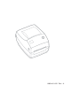
Introduction This section describes what you get in your shipping box and provides an overview of printer parts. This section also has procedures that describe how to open and close the printer and report any problems. Hello! ® Thank you for choosing a Zebra TLP 3844-Z™ printer, a high-quality on-demand printer manufactured by the industry leader in quality, service, and value—Zebra Technologies Corporation.
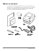
What’s in the Box? Save the carton and all packing materials in case you need to ship or store the printer later. After unpacking, make sure you have all parts. Follow the procedures for inspecting the printer to familiarize yourself with printer parts so you can follow the instructions in this book. 2 980441-001 Rev.
Inspecting the Printer Look at the outside of the printer and make sure that all parts are present. Opening the printer To access the media compartment, you must open the printer. Pull the release levers towards you and lift the cover. 980441-001 Rev.
INSPECTING THE PRINTER (continued) After opening the printer, check the media compartment. 4 980441-001 Rev.
Closing the printer Hold the top cover and press the “kick-stand” cover lock to release. MOVIE Lower the top cover. The ribbon carriage automatically folds up into place. Press down until the cover snaps closed. 980441-001 Rev.
Reporting Damage If you discover damage or missing parts: ■ Immediately notify and file a damage report with the shipping company. Zebra Technologies Corporation is not responsible for any damage incurred during shipment of the printer and will not cover the repair of this damage under its warranty policy. ■ Keep the carton and all packing material for inspection.
Getting Started This section describes how to set up your printer for the first time and use the most common operating procedures for loading media in tear-off mode and loading ribbon. Modes of Printing You can operate this printer in different modes: ■ Standard tear-off mode allows you to tear off each label (or a strip of labels) after it is printed. ■ In optional peel-off mode, the backing material is peeled away from the label as it is printed. After this label is removed, the next one is printed.
Attaching Power Supply Check the power supply to make certain it is appropriate for your input voltage. Warning: Use the Zebra-supplied power supply that came with your printer. Never operate the printer and power supply in an area where they can get wet. Serious personal injury could result! 1. Make sure the power switch is in the off position (down). 2. The DC power supply has a barrel connector on one end that must be inserted into the power supply receptacle on the back of the printer. 3.
Loading Roll Media When you load media, you must place the roll on the media hangers and then adjust the media guides. MOVIE You must use the correct media for the type of printing you require. When printing without a ribbon, you must use direct thermal media. When using ribbon, you must use thermal transfer media. The printer's ribbon sensor detects motion of the supply spindle.
Adjusting the Guides The adjustable guides direct the media toward the platen and print head. 1. Open the media guides by turning the guide adjuster knob to the rear. 2. Thread the media through the guides. 3. Close the media guides by turning the guide adjuster knob to the front. They should just touch, but not restrict, the edges of the media. 4. Unless you need to load ribbon, close the top cover.
Loading Ribbon MOVIE You must use thermal transfer media (accepts wax and/or resin transferred off a ribbon) when you use a ribbon. When loading ribbon, you install the supply and take-up rolls, then tighten the ribbon on the carriage. Install the Ribbon Supply Roll Before following these steps, prepare the ribbon by removing its wrapping and pulling its adhesive strip free. 1. Thread the ribbon through the carriage. 2. Press the right side onto the supply hub. 3.
Attach and Tighten the Ribbon You must align the ribbon so that it will be taken straight onto the core. 1. Attach the ribbon to the take up core. Use the adhesive strip on new rolls; otherwise, use tape. 2. Turn the ribbon take-up gear counter-clockwise (top moves toward rear) to remove slack from the ribbon. 3. Close the top cover. Remember that you need to release the cover lock, lower the top cover, and press down until the latches snap into place. 12 980441-001 Rev.
Auto Calibration NOTE: If you are using pre-printed labels, pre-printed label backing, or continuous media, see “Manual Calibration” on page 40. An auto calibration is performed when the printer is turned on (if media is loaded) or after a media error is cleared. When it is auto calibrating, the printer sets the sensor levels for, and determines the length of, the label you are using. If the status light flashes red, refer to “Manual Calibration” on page 40. 980441-001 Rev.
Operator Controls Power Switch Press up to turn ON or down to turn OFF the printer. CAUTION: The power should be turned off before connecting or disconnecting the communications and power cables. Feed Button Forces the printer to feed one blank label. Takes the printer out of a “pause” condition. (The printer is put into “pause” by either a ZPL II command or an error condition.) See “What the Status Light is Telling You” on page 35.
Printing a Test Printout Before you connect the printer to your computer, make sure that the printer is in proper working order. You can do this by printing a configuration printout. 1. Make sure the media is properly loaded and the top cover of the printer is closed. Then, turn the printer power on if you have not already done so. 2. When the status light is solid green, press and hold the feed button until the status light flashes once. 3. Release the feed button.
Hooking Up the Printer and Computer Your printer will have one of two combinations of interfaces: ■ Universal Serial Bus (USB), parallel and serial ■ USB, Ethernet (using the Internal ZebraNet® PrintServer II™) and serial MOVIE Each specific interface option—USB, parallel, Ethernet, serial—is discussed individually. You must supply the required interface cable for your application. CAUTIONS:Keep the power switch in the OFF position when attaching the interface cable.
USB Interface Requirements Universal Serial Bus (version 1.1) provides a high-speed interface that is compatible with your existing PC hardware. USB’s “plug and play” design makes installation easy. Multiple printers can share a single USB port/hub. Parallel Interface Requirements The required cable (IEEE 1284-compliant is recommended) must have a standard 36-pin parallel connector on one end, which is plugged into the parallel port located on the back of the printer.
Communicating with the Printer Universal Serial Bus (USB) Communications The printer is a terminal device when using a universal serial bus interface. You can refer to the Universal Serial Bus Specification for details regarding this interface. Parallel Communications When using the parallel port, typically there is no setup is required once the cable is plugged in. If you should encounter any problems, consult the user’s guide that came with your computer.
Serial Communications (Continued) ^SC Command Use the Set Communications (^SC) command to change the communications settings on the printer. 1. With the host computer set at the same communications settings as the printer, send the ^SC command to change the printer to the desired settings. 2. Change the host computer settings to match the new printer settings. Refer to the ZPL II Programming Guide for more information about this command.
Adjusting the Print Width Print width must be calibrated when: ■ You are using the printer for the first time. ■ There is a change in the width of the media. Print width may be set by way of the five-flash sequence in “Feed Button Modes” (see page 43) or refer to the Print Width (^PW) command (consult your ZPL II Programming Guide).
Operation & Options This section helps you get the most from your printer. You must use programming to control many of the printer’s functions. A few examples: ■ The ~JL command controls label length. ■ The ^XA^MTD^XZ command changes the printing mode to direct thermal; the ^XA^MTT^XZ command changes the printing mode to thermal transfer. ■ The ^XA^JUS^XZ command saves the new settings to flash memory.
Replacing Supplies If labels or ribbon run out while printing, leave the printer power on while reloading (data loss results if you turn off the printer). After you load a new label or ribbon roll, the printer flashes double-green until you press the Feed button to restart . Always use high quality, approved labels, tags and ribbons.
Printing in Peel-Mode ON OFF The optional dispenser allows you to print in “peel-mode” where the label backing follows a different path and the labels are presented one at a time for subsequent placement. Before using peel-mode, you must send the programming commands ^XA ^MMP ^XZ ^XA ^JUS ^XZ to the printer. Refer to your ZPL II Programmer’s Manual. 1. Remove several labels from the backing material. 2. Open the top cover. 3. Open the dispenser door. 4. Switch on the label-taken sensor. 5.
Printing on Fan-Fold Media Printing on fan-fold media requires you to set both the media hangers and the media guides in position. Lock-down Screw 1. Open the top cover. 2. With a sample of your media, adjust the media hangers to the width of the media. The hangers should just touch, but not restrict, the edges of the media. 3. Tighten the screw using a small Phillips driver #1. 4. With a sample of your media, adjust the guides to the width of the media.
Using the Cutter Option Printers that have a bezel with a motorized blade can dispense one or more forms that are then automatically cut from the media supply. This option cuts through continuous paper from rolls and liner between labels. Keep the cutter dry. Never use any solutions or solvents to clean the blade. Use the ^MM command to activate the cutter and the ^LL command to set the form length and gap distance. See the ZPL II programmer's manual.
26 980441-001 Rev.
Maintenance Cleaning When you clean the printer, use one or more of the following supplies that best suits your needs: DESCRIPTION Cleaning pens (12) Cleaning swabs (25) Cleaning cards, 4-in wide (25) Save-a-Print Head film, 4-in wide (3) The cleaning process takes just a couple of minutes using the steps outlined below. Printer Part Method Let the print head to cool for one minute, then use a new cleaning pen to swab the print elements (the thin gray line on the print head) from end to end.
Adhesives and coatings of media can over time transfer onto the printer components along the media path including the platen and print head. This build-up can accumulate dust and debris. Failure to clean the print head, media path and platen roller could result in inadvertent loss of labels, label jams and possible damage to the printer. Print Head Considerations MOVIE Always use a new cleaning pen on the print head (an old pen carries contaminants from its previous uses that may damage the print head).
Platen Considerations The standard platen (drive roller) normally does not require cleaning. Paper and liner dust can accumulate without effecting print operations. Contaminates on the platen roller can damage the print head or cause the media to slip when printing. Adhesive, dirt, general dust, oils and other contaminates should be cleaned immediately off the platen.
Replacing the Platen Removal MOVIE Open the printer and remove any media. 1. Using a pointed stylus (such as tweezers, small slot-head screwdriver, or razor-knife), unhook the tabs on the right and left sides. Then rotate them forward. 2. Lift the platen out of the printer’s bottom frame. Assembly Make sure the right bearing is on the shaft of the platen. 1. Align the platen with the gear to the left and lower it into the printer’s bottom frame. 2. Rotate the tabs back and snap them into place.
Replacing the Print Head In the event you need to replace the print head, read the procedure and review the removal and installation steps before actually replacing the print head. Prepare your work area by protecting against static discharge. Your work area must be static-safe and include a properly grounded conductive cushioned mat to hold the printer and a conductive wrist strap for yourself. MOVIE NOTE: Turn the printer power off and unplug the power cord before replacing the print head.
Thermal-Transfer TLP Model Before following the steps in this MOVIE procedure, open the printer by pulling the release latches forward then lifting the top cover. Remove any ribbon from the carriage. Removal 1. Grasp the print head spring and pull it to the left; then, slide it free of the carriage. 2. Use the spring to pry the print head clip off the right side of the carriage. 3. Pull the print head and bracket forward. 4. Use a #2 Phillips driver to remove the screw that holds the ground wire. 5.
Replacing the TLP Print Head (Continued) Assembly The new print head comes with the clip and ground screw attached. 1. Align the print head and bracket to plug the left and right connectors into the black and white wire bundles. 2. Attach the ground wire and secure it with the screw. Use a #2 Phillips driver to tighten it. 3. Insert the bracket pegs into the left side of the carriage. 4.
34 980441-001 Rev.
Troubleshooting What the Status Light is Telling You Status LED Condition and Color Printer Status For a Resolution, Refer to number: Off Off 1 Solid Green On 2 Flashing Amber Stopped 3 Flashing Green Normal Operation 4 Flashing Red Stopped 5 Double Flashing Green Paused 6 Solid Amber Various 7 Alternately Flashing Green and Red Needs Service 8 Resolutions 1. The printer is not receiving power.
3. The printer has failed its power on self test (POST). ■ If this error occurs right after you turn on the printer, contact an authorized reseller for assistance. There is a shortage of memory. ■ If this error occurs after you have been printing, turn the printer power off and on. Then, resume printing. 4. The printer is receiving data. ■ As soon as all of the data has been received, the status LED will turn green; then, the printer will automatically resume operation. 5.
7. The print head is under temperature. ■ Continue printing while the print head reaches the correct operating temperature. The print head is over temperature. ■ Printing will stop until the print head cools to an acceptable printing temperature. When it does, the printer will automatically resume operation. 8. FLASH memory is not programmed. ■ Return the printer to an authorized reseller. 980441-001 Rev.
Print Quality Problems No print on the label. ■ You must use the correct media for the method of printing you require. When printing without a ribbon, you must use direct thermal media. When using ribbon, you must use thermal transfer media. The printer's ribbon sensor detects motion of the supply spindle. ■ Is the media loaded correctly? Follow the instructions in “Loading the Media” on page 9. The printed image does not look right. ■ The print head is dirty.
The printing does not start at the top of the label, or misprinting of one to three labels. ■ The media may not be threaded under the media guides. Refer to “Loading the Media” on page 9. ■ The printer needs to be calibrated. Refer to “Auto Calibration” on page 13. ■ The correct media sensor may not be activated. Manual calibration selects the media sensing method for the labels being used (refer to the ^MN command in the ZPL II Programming Guide).
Manual Calibration Manual calibration is recommended whenever you are using pre-printed media or if the printer will not correctly auto calibrate. MOVIE 1. Make sure media is loaded. 2. Turn on the printer power. 3. Press and hold the feed button until the green status LED flashes once, then twice. Release the feed button. 4. The printer will set the media sensor for the label backing being used.
Troubleshooting Tests Printing a Configuration Label To print out a listing of the printer’s current configuration, refer to the one-flash sequence in “Feed Button Modes” on page 43. Recalibration Recalibrate the printer if it starts to display unusual symptoms, such as skipping labels. See “Auto Calibration” on page 13. 980441-001 Rev.
Resetting the Factory Default Values Sometimes, resetting the printer to the factory defaults solves some of the problems. Follow the four-flash sequence instructions in “Feed Button Modes” on page 43. Communications Diagnostics MOVIE 42 If there is a problem transferring data between the computer and printer, try putting the printer in the communications diagnostics mode.
Feed Button Modes MOVIE Power Off Mode (Communications Diagnostics Mode) With the printer power off, press and hold the feed button while you turn on the power. The printer prints out a listing of its current configuration. After printing the label, the printer will automatically enter a diagnostic mode in which the printer prints out a literal representation of all data subsequently received. To exit the diagnostic mode and resume printing, turn off and then turn on the printer.
44 980441-001 Rev.
Appendix Specifications Physical Specifications Size 7.8 inches wide / 6.8 inches tall / 9.4 inches long (depth) 200 mm wide / 173 mm tall / 240 mm long (depth) Weight 3.6 pounds / 1.6 kilograms Environmental Guidelines Operating temp. 40 to 104 degrees Fahrenheit / 5 to 40 degrees Celsius Operating humidity 10 to 90 percent non-condensing Storage temp.
Media Specifications Width 1 to 4.25 inches / 25.4 to 108 millimeters) Length 0.5 to 39 inches / 13 to 559 millimeters with standard memory Gap 0.08 to 0.16 inch (2.0 to 4.0 millimeters) 0.118 inch / 3.0 millimeters recommended Thickness 0.003 to 0.007 inch / 0.08 to 0.18 millimeter Roll Size Maximum outer diameter: 5 inches (127 millimeters) Inner Core diameters: 1 or 1.5 inches (25.
Font/Code Specifications Fonts ✔ CG Triumvirate Bold Condensed scalable smooth (0) ✔ Zebra fonts A-H, GS, P-V ✔ IBM Code Page 850 international Symbols 1D Bar Codes ✔ Codabar (supports ratios of 2:1 to 3:1) ✔ Code 11 ✔ Code 128/USD 8 (supports serialization in all subsets and UCC Case Codes) ✔ Code 39 (supports ratios of 2:1 to 3:1) ✔ Code 93 ✔ EAN 8/JAN 8 ✔ EAN 13/JAN 13 ✔ EAN 14/UPC-A ✔ Industrial 2 of 5 ✔ Standard 2 of 5 ✔ Interleaved 2 of 5 (supports ratios of 2:1 to 3:1, Modulus 10 Check Digit) ✔ L
Agency Approvals The thermal-transfer printer model TLP 3844-Z, manufactured by Zebra Technologies Corporation, complies with the applicable requirements: SUBJECT Emissions AGENCY COUNTRIES STANDARDS FCC United States Part 15, Subpart B VCCI Japan V-3/93.
Interfaces Universal Serial Bus (USB) Connector The figure below displays the cable wiring required to use the printer’s USB interface. 2 3 1 4 Pin Signal 1 Vbus - N/C 2 D- 3 D+ 4 Ground Shell Shield/ Drain Wire For printer supported operating systems and drivers, see the software and documentation CD or visit the Zebra printer web site at: http://www.zebra.com For information on the USB interface, go to the USB web site at: Http://www.usb.org 980441-001 Rev.
Parallel Interface The maximum current available through the interface port is not to exceed a total of 0.75 amps. 50 Pin No. Description 1 NStrobe/Host Clk 2-9 Data Bits 1-8 10 nACK/PtrClk 11 Busy/Per Busy 12 PError/ACK Dat Req. 13 Select/Xflag 14 NAuto Fd/Host Busy 15 Not Used 16-17 Ground 18 +5 V @ 0.75 A Fused 19-30 Ground 31 nInit 32 NFault/nData Avail. 33-34 Not Used 35 +5 V throught 1.8 K Ohms Resistor 36 NSelectin/1284 active 980441-001 Rev.
ZebraNet® PrintServer II for Ethernet Networks This interface uses an RJ-45 straight-through cable type. The table below provides the pinout assignments.
Serial (RS-232) Connector Pin No. Description 1 Not used 2 RXD (receive data) input to the printer 3 TXD (transmit data) output from the printer 4 DTR (data terminal ready) output from the printer -- controls when the host may send data 5 Chassis ground 6 DSR (data set ready) input to the printer 7 RTS (request to send) output from the printer -- always in the ACTIVE condition when the printer is turned on 8 Not Used 9 +5 V @ 0.
Connecting the Printer to a DTE Device DB-25S Connector to DTE Device (PC) 2 3 4 5 6 7 8 20 22 TXD RXD RTS CTS DSR GND DCD DTR DB-9P Connector to Printer DCD RXD TXD DTR GND DSR RTS CTS 1 2 3 4 5 6 7 8 9 DB-9S Connector to DTE Device (PC) 1 2 3 4 5 6 7 8 9 DCD RXD TXD DTR GND DSR RTS CTS DB-9P Connector to Printer DCD RXD TXD DTR GND DSR RTS CTS 1 2 3 4 5 6 7 8 9 Connecting the Printer to a DCE Device DB-25S Connector to DCE Device 2 3 4 5 6 7 8 20 22 RXD TXD CTS RTS DTR GND DCD DSR 980441-001 Rev
54 980441-001 Rev.
Index A agencies . . . . . . . . . . . . . . . . . . . . . . . 48 attaching power . . . . . . . . . . . . . . . . . . 8 auto calibration . . . . . . . . . . . . . . . . . 13 autobaud . . . . . . . . . . . . . . . . . . . . . . 18 B bar codes . . . . . . . . . . . . . . . . . . . . . . 47 barrel connector. . . . . . . . . . . . . . . . . . 8 box, contents . . . . . . . . . . . . . . . . . . . . 2 button, feed . . . . . . . . . . . . . . . . . . . . 14 C cable . . . . . . . . . . . . . . . . . . . . . . . . .
I inspecting printer. . . . . . . . . . . . . . . . . 3 interface. . . . . . . . . . . . . . . . . . . . . . . 16 ethernet. . . . . . . . . . . . . . . . . . . . . 17 parallel . . . . . . . . . . . . . . . . . . . . . 17 serial . . . . . . . . . . . . . . . . . . . . . . . 17 USB . . . . . . . . . . . . . . . . . . . . . . . 17 interface connectors . . . . . . . . . . . . . . 3 L light, status . . . . . . . . . . . . . . . . . . . . 14 loading media . . . . . . . . . . . . . . . . . . . 9 loading ribbon . .
R recalibrating the printer . . . . . . . . . . . 41 related documentation . . . . . . . . . . . . . 6 release latches . . . . . . . . . . . . . . . . . . . 3 replace the print head . . . . . . . . . . . . 31 replacing supplies . . . . . . . . . . . . . . . 22 resetting the factory defaults . . . . 42, 43 ribbon . . . . . . . . . . . . . . . . . . . . . . . . 22 ribbon carriage . . . . . . . . . . . . . . . . . . 4 ribbon sensor printout . . . . . . . . . . . . 38 ribbon specifications . . . . . . . . . . .