___________________________________________________________________________ User Guide WhereCall IV User’s Guide WhereCall IV Part Number TFF-2220-00AA WhereCall IV PLC Part Number TFF-2221-00AA ___________________________________________________________________________ 1 TFF-2220-00AA and TFF-2221-00AA User’s Guide D1436 Rev B ©2008 Zebra Enterprise Solutions. WhereCall IV and all product names and numbers are Zebra Enterprise Solutions trademarks.
___________________________________________________________________________ User Guide User Guide Special Notices Warnings call attention to a procedure or practice that could result in personal injury if not correctly performed. Do not proceed until you fully understand and meet the required conditions. ________ Cautions call attention to an operation procedure or practice that could damage the product if not correctly performed.
___________________________________________________________________________ User Guide FCC Requirements Zebra Enterprise Solutions is a division of Zebra Technologies Corporation. The following regulatory agency information is for Model TFF-2220 devices, which includes part numbers TFF-2220-00AA and TFF-2221-00AA. FCC Compliance Statement This device complies with Part 15 rules.
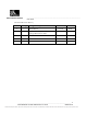
___________________________________________________________________________ User Guide Document Revision History Revision Change A B C01769 Change Description Date Author Initial Release 2/3/09 DCB Update mounting bracket photos and change WhereNet to ZES 6/10/09 DCB ___________________________________________________________________________ 4 TFF-2220-00AA and TFF-2221-00AA User’s Guide D1436 Rev B ©2008 Zebra Enterprise Solutions.
___________________________________________________________________________ User Guide Table of Contents Page 1 Overview 7 2 Components 9 2.1 ISO 24730 System 9 2.1 CCX System 10 3 Installation & Mounting 11 3.1 Poly-Lock 11 3.2 Mounting WhereCall IV with Poly-Lock 12 3.3 WhereTag Foam Tape Squares 13 3.4 Mounting WhereCall IV with Foam Tape Squares 14 3.5 Cable Hanging Mounting Bracket 15 3.6 Installing WhereCall IV with Cable Hanging Bracket 16 3.
___________________________________________________________________________ User Guide 8.1 WhereCall IV PLC FCC Requirements 35 8.2 WhereCall IV PLC Overview 36 8.3 WhereCall IV PLC Installation & Mounting 37 8.
___________________________________________________________________________ User Guide 1 OVERVIEW The Zebra Enterprise Solutions (ZES) WhereCall System allows users in manufacturing and assembly operations to request service or specific parts without leaving their workstations. Specific parts or service requests may be assigned to individual WhereCall IV devices so that users may indicate which item is needed.
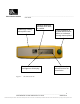
___________________________________________________________________________ User Guide Durable high visibility yellow plastic case Flashing apostrophe indicates CCX mode is enabled Easy to read 8-character, 14-segment LCD display Figure 1: Large pushbutton to activate WhereCall IV blinks or to advance through menu options Flashing decimal indicates ISO 24730 transmission The WhereCall IV ___________________________________________________________________________ 8 TFF-2220-00AA and TFF-2221-00AA Use
___________________________________________________________________________ User Guide 2 2.1 COMPONENTS ISO 24730 System The WhereCall ISO 24730 System consists of four major components: the WhereCall IV device; a location antenna; a location processor and a ZES computer server. This document details only the WhereCall IV device. The WhereCall IV is a palm-sized device approximately 6.3 inches by 1.7 inches, 1.2 inch thick, in a yellow case.
___________________________________________________________________________ User Guide 2.1 CCX System The CCX System consists of four major components: the WhereCall IV device; CCX access points; a wireless LAN controller and a location processor. This document details only the WhereCall IV device. The WhereCall IV is a palm-sized device approximately 6.3 inches by 1.7 inches, 1.2 inch thick, in a yellow case. A green colored actuator button is on the right side of the device.
___________________________________________________________________________ User Guide 3 INSTALLATION & MOUNTING The WhereCall IV may be mounted in a work area with removable fasteners, double-coated foam tape, hanging brackets, or with mounting screws. . The WhereCall IV display is optimized for viewing at an angle perpendicular from the operator or from above. Mounting the WhereCall IV above an operator’s eyelevel does not provide maximum contrast for the LCD display.
___________________________________________________________________________ User Guide Apply the Poly-Lock squares to these two locations Figure 3: _________ CAUTION _________ 3.2 Poly-Lock positions Mounting WhereCall IV with Poly-Lock Do not apply the poly-lock when the temperature is below 60°F (15°C) or above 90°F (32°C). 1. Select the desired location in the workstation to mount the WhereCall IV. 2. Clean the mounting surface and the back cover of the WhereCall IV with isopropyl alcohol.
___________________________________________________________________________ User Guide 3. Select two pairs (they are shipped in attached pairs)of Poly-Lock squares, remove the adhesive backing on one side of each pair, and then press them to the tag case, sticky side down as shown in Figure 3. 4. You should now have two pairs of Poly-Lock attached to the back of the WhereCall IV. Remove the adhesive backing from both squares. 5.
___________________________________________________________________________ User Guide Apply the Foam Tape squares to these two locations Figure 5: 3.4 Foam tape squares Mounting WhereCall IV with Foam Tape Squares ________ Do not apply the foam tape when the temperature is below 60°F (15°C) or above 90°F (32°C). CAUTION ________ 1. Select the desired location to mount the WhereCall IV. 2. Clean the mounting surface and the back plate of the WhereCall IV with isopropyl alcohol. 3.
___________________________________________________________________________ User Guide 4. Remove the adhesive backing from the exposed surface of the tape squares. 5. While holding the WhereCall IV, aligned to the desired position. Gently press the unit onto the mounting surface. 3.5 Cable Hanging Mounting Bracket The WhereCall IV may also be installed from an overhead cable for ease of use in a workstation where mounting on flat surfaces is unsafe or inconvenient.
___________________________________________________________________________ User Guide Remove and save these 4 screws Figure 7: 3.6 Attaching WhereCall IV to Mounting Bracket Installing WhereCall IV with Cable Hanging Bracket 1. Using a 5/64 inch hex drive bit, remove 4 screws from the bottom cover as shown in Figure 7. 2. Align the mounting bracket so the 4 screw holes align with the 4 screw holes in the WhereCall IV bottom cover.
___________________________________________________________________________ User Guide Figure 8: 3.7 Cable Hanging Bracket Installed Screw Mounting Bracket The WhereCall IV may be installed using screw by utilizing the screw mounting bracket. Screw mounting brackets are not included with the WhereCall IV but are available from ZES. Contact your ZES Account Manager for information, reference part number TM-240-00.
___________________________________________________________________________ User Guide 3.8 Installing WhereCall IV with Screw Mounting Bracket 1. Using a 5/64 inch hex drive bit, remove 4 screws from the bottom cover as shown in Figure 7. 2. Align the mounting bracket so the 4 screw holes align with the 4 screw holes in the WhereCall IV bottom cover. Be sure the four counter sunk holes in the mounting bracket are visible and not against the WhereCall IV bottom cover.
___________________________________________________________________________ User Guide 4 OPERATION OF THE WHERECALL IV The WhereCall IV is a wireless messaging device that is capable of transmitting simple messages to the ZES Infrastructure. These messages can range from a call for parts for line side material replenishment to a request for supervisor assistance.
___________________________________________________________________________ User Guide 4.1 Call Mode In CALL mode the WhereCall IV can be used for parts call and other operations that do not require an indication as to whether the request was fulfilled. In this mode, the operator presses the button to send the request message, and the WhereCall IV will transmit blinks with “Switch ID 0” which has status 2.
___________________________________________________________________________ User Guide 4.2 Switch Mode In switch mode, the display toggles between -- ON -- and -- OFF -- . The normal starting state is OFF. If the operator presses the button, then the WhereCall will send a message signaling the change in state and the display will change to -- ON --. The resulting transmission blink includes “Switch ID 0” which has status 2.
___________________________________________________________________________ User Guide 4.3 Turning WhereCall IV Off The WhereCall IV can be switched to the Power OFF mode from either CALL mode or SWITCH mode. In order to do this, press and hold the button until the display shows ******** and then release the button. The display will show the tag firmware version TAG 2109 for a few seconds and then show the PIC Microcontroller firmware PIC 1017 version for a few seconds, the show PWR OFF .
___________________________________________________________________________ User Guide 4.5 Changing System Protocols To change the WhereCall IV mode between ISO 24730, CCX, and dual mode, the WhereCall IV must be in OFF mode and display PWR OFF . Press and hold the button for several seconds until the display starts to cycle between these options… ISO MODE , CCX MODE , DUALMODE , and CNG BATT .
___________________________________________________________________________ User Guide 4.6 WhereCall IV Soft Messages The WhereCall IV supports soft messaging which allows the user to replace the displayed messages CALL , --—ON -- and/or -—OFF -- with custom messages. Setting or changing the soft message will require a WhereWand to enter and program the messages to the WhereCall IV magnetically. If a custom message is configured in CALL mode, then the custom message will be displayed.
___________________________________________________________________________ User Guide 4.7 ____________ CAUTION ____________ Changing the WhereCall IV Batteries Caution: Personnel changing batteries must use an ESD wrist strap to prevent damage of the tag circuit board due to static discharge. Follow the manufacturer’s instructions for proper use of the static prevention device. 4.7.1 Description WhereCall IV Tags have a nominal battery life of 5 years.
___________________________________________________________________________ User Guide 4.7.3 Tools ZES does not provide the required materials and tools for changing batteries with the WhereCall IV Tags. The following tools will be required to change the WhereCall IV batteries. • One, torque wrench with a 5/64 inch hex drive bit and the torque set to 6.0 + .6 inchpounds [0.68 + 0.07 Newton-meters] for the six screws on the bottom cover of the tag.
___________________________________________________________________________ User Guide Step 3: Remove both of the old batteries and dispose of properly. Step 4: Install two new batteries, being careful to orient the batteries correctly and not to install either battery backwards. Refer to figure 11 for proper battery orientation. Note battery orientation.
___________________________________________________________________________ User Guide 5 Display Message WHERECALL IV LCD DISPLAY MESSAGES Display Meaning Comments Action required “CALL ” (flashing) CustCall CALL mode button blinks are being transmitted. This mode will continue for 60 None seconds following a button press. (flashing) “CALL ” 10h 42m This display follows the Call” (alternating) display and indicates the elapsed time from the last CustCall button press.
___________________________________________________________________________ User Guide Display Message CALL ? SWITCH ? ISO MODE CCX MODE DUALMOD E CNG BATT (cycling) CCX MODE DUALMOD E CNG BATT ISO MODE (cycling) Display Meaning Indicates that the user has held the button for several seconds and can now change mode from SWITCH mode to CALL mode if desired. Indicates that the user has held the button for several seconds and can now change mode from CALL mode to SWITCH mode if desired.
___________________________________________________________________________ User Guide Display Message DUALMOD E CNG BATT ISO MODE CCX MODE (cycling) CNG BATT ISO MODE CCX MODE DUALMOD E (cycling) CHANGE BATTERY (alternating) Display Meaning DUALMODE indicates the user has pressed and held the button for several seconds while in PWR OFF state and can now put the tag into an unsupported mode CNG BATT indicates the user has pressed and held the button for several seconds while in PWR OFF state and can n
___________________________________________________________________________ User Guide 6 SPECIFICATIONS: WHERECALL IV DEVICE Specifications are subject to change without notice. Mechanical Dimensions 6.45 x 1.74 x 1.27 inches [163.8 x 44.2 x 32.3 mm] nominal Weight 6.3 ounces [180 grams] nominal Color High Visibility Yellow and Light Gray Attachments Mounting Brackets, Poly-Lock, or Foam Tape Form Factor Wall Mounted-Rugged Aesthetics Durability Drop 4 feet [1.
___________________________________________________________________________ User Guide Connector (used with WhereCall IV PLC) Mating Connector Waterproof, 4 pin, mates with Turck RS-4.41T-X (where X is the cable length) or equivalent Display Characteristics Number of Characers 8 Format 14-Segment with apostrophe and decimal for each character Function Check previous page Digit Size .
___________________________________________________________________________ User Guide 7 CONFIGURABLE PARAMETERS The WhereCall IV is configured with a default configuration suitable for most applications during the manufacturing process. If desired, the WhereCall IV can be reconfigured using a WhereWand. The following table identifies the configurable parameters. Valid ranges for each parameter are determined by the WhereWand.
___________________________________________________________________________ User Guide 8 WHERECALL IV PLC WhereCall IV PLC User & Interface Guide ___________________________________________________________________________ 34 TFF-2220-00AA and TFF-2221-00AA User’s Guide D1436 Rev B ©2008 Zebra Enterprise Solutions. WhereCall IV and all product names and numbers are Zebra Enterprise Solutions trademarks. All other trademarks are the property of their respective owners.
___________________________________________________________________________ User Guide 8.1 WhereCall IV PLC FCC Requirements This device must operate in compliance with Federal Communications Commission (FCC) Rules and Regulations Parts 15. See FCC registration label, located on the bottom of the equipment, for the FCC registration. This equipment has been tested and found to comply with the limits for both Class A and Class B devices, pursuant to Part 15 of the FCC Rules.
___________________________________________________________________________ User Guide 8.2 WhereCall IV PLC Overview This document describes how to mount and interface the WhereCall IV PLC to your equipment via the external industrial connector. The WhereCall IV PLC is a variation of the standard WhereCall IV. It allows the call tag to be used with a remote switch in external equipment. The external equipment can “press the button” to initiate a call.
___________________________________________________________________________ User Guide 8.3 WhereCall IV PLC Installation & Mounting The WhereCall IV PLC may be mounted in a work area with removable fasteners, doublecoated foam tape, hanging brackets. Each WhereCall IV PLC must be mounted in a location to provide an unobstructed view to a location antenna in at least one direction.
___________________________________________________________________________ User Guide 8.4 Connecting the WhereCall IV PLC The WhereCall IV PLC can be connected to a remotely mounted switch that is used to initiate a “button blink”. This product works very much like the WhereCall IV except that “button” actuation is provided from another device. 8.4.1 WhereCall IV PLC Cable and Connector. The TFF-2221 is to be connected using a Turck, RS 4.41T-X cord-set. The length of the cable is limited to 3.
___________________________________________________________________________ User Guide 8.4.2 WhereCall IV PLC Electrical Connection. Pins one (1) and three (3) are to be connected to the remote switch. The external switch is connected across pins 1 and 3 as indicated Figure 12: WhereCall IV PLC Connector ____________ Note Use the reference detail on the connector to identify the pin numbers. The connector may not be oriented the same on all units.
___________________________________________________________________________ User Guide WhereTag IV PLC Interface Cable Electrical Block Diagram The momentary switch will initiate blinks when it is closed for 100 milliseconds and then released. The switch must not remain closed for more than 3.0 seconds to avoid switching to power off mode. Turck RS 4.
___________________________________________________________________________ User Guide 8.4.3 WhereCall IV PLC Switch Operation The switch used to operate the TFF-2221 must be a momentary type. The TFF-2221 will initiate a “Button Blink” sequence when the switch breaks after having been closed for at least 100ms and less than 5 s. It the switch is closed for less than 100 ms the unit will not react. See Table 1 for more information.