
User's Guide

4
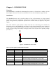
Table 2 - Pin Description of RADAR-Side 9-Pin Female
Pin Number Pin Name Description
1 GND Ground
2 Serial_Out RS-232 Output
3 Serial_In RS-232 Input
4 GND Ground
5 GND Ground
6 POWER_IN Input DC Power – Approximately 200mA @ +5V.
Input DC Voltage can range from +3V to +30V.
7 Loop Connected to Pin 8
8 Loop Connected to Pin 7
9 POWER_IN Input DC Power – Approximately 200mA @ +5V.
Input DC Voltage can range from +3V to +30V.
1
5
6 9
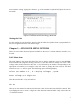
Figure 2 – Communication Port Location
Chapter 2 – BASIC SETUP
This chapter describes the process for setting up a terminal window on a user’s computer. The
below procedure assumes the user is running Windows 2000. Since other versions of Windows
may deviate slightly from the following procedure, the user should check the operating system
user’s manual for proper terminal setup procedures.
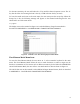
HyperTerminal Setup
To setup a HyperTerminal window under Windows 2000, adhere to the following procedure.
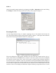
STEP 1:
Navigate to the Programs -> Accessories -> Communications folder and select the
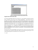
HyperTerminal icon. You should see a window similar to the one shown in Figure 3. Type a
name for your HyperTerminal Session. The example below uses the “SPIDER-650” name. Once
you have typed a name, click the OK button.