SPIDER-650 Short Pulse Digital RADAR User’s Guide MULTISPECTRAL SOLUTIONS, INC.
Note 1: General Conditions of operation (FCC 15.5) This device complies with Part 15 of the FCC Rules. Operation is subject to the following two conditions: (1) this device may not cause harmful interference, and (2) this device must accept any interference received, including interference that may cause undesired operation. Note 2: Modifications (FCC 15.21) Changes or modifications to this equipment not expressly approved by Multispectral Solutions, Inc.
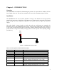
Chapter 1 – INTRODUCTION Overview The SPIDER-650 is intended for determining the presence of objects that are within a 50-foot line-of-sight of the unit. The unit has a resolution of 1 foot with a maximum range of 50 feet. Installation The SPIDER-650 unit can be placed anywhere as long as the antennae are facing outward towards the open space of detection. The antennae are located on the side with the elevated plastic facing.
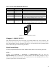
Table 2 - Pin Description of RADAR-Side 9-Pin Female Pin Number 1 2 3 4 5 6 7 8 9 Pin Name GND Serial_Out Serial_In GND GND POWER_IN Loop Loop POWER_IN Description Ground RS-232 Output RS-232 Input Ground Ground Input DC Power – Approximately 200mA @ +5V. Input DC Voltage can range from +3V to +30V. Connected to Pin 8 Connected to Pin 7 Input DC Power – Approximately 200mA @ +5V. Input DC Voltage can range from +3V to +30V.
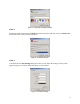
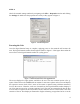
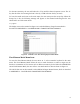
Figure 3 - Connection Description Window STEP 2: Determine which serial port the SPIDER-650 unit is attached to and enter it in the “Connect To” box shown below. Then click the OK button. Figure 4 - Serial Port Selection STEP 3: You should see the Port Settings dialog box come up next. Enter the settings exactly as they appear in Figure 5. Click the OK button when you are finished.
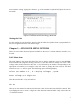
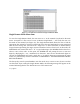
STEP 4: Check the terminal settings window by navigating to the File -> Properties window and clicking the Settings tab. Make sure the properties are exactly as they appear in Figure 6. Figure 6 - Terminal Properties Powering the Unit Once the HyperTerminal setup is complete, applying power to the terminals will activate the unit. The HyperTerminal window should appear similar to Figure 7. This figure shows what the user will see in the HyperTerminal window on cycling power.
most sensitive setting. Typing the character ‘g’ on the terminal’s keyboard will place the user in this mode. Figure 8 - Terminal Screen after Executing 'g' Menu Item Aiming the Unit For best results, the unit should be aimed so that the white-faced plastic front is perpendicular to the line-of-sight between the unit and the target. Chapter 3 – ADVANCED MENU OPTIONS There are seven other advanced options available to the user if a custom software interface is to be used.
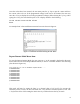
Once the values have been entered, the user must press the ‘q’ key to quit the menu and force the current value to be set. If the programmed voltage levels need to be obtained, the user may enter the ‘d’ key to display the currently programmed voltages (before hitting the ‘q’ key). After typing the ‘d’key, the user should expect to see a display similar to the following: v1=10 v2=30 v3=60 v4=50 v5=90 done An example DAC value modification terminal screen is shown in Figure 9.
To decrease sensitivity, the user will strike the ‘d’ key until the desired response is seen. The ‘d’ key has the effect of increasing the DAC value by 1 LSB each time the key is struck. To leave this mode and return to the main menu, the user must press the escape key.
Figure 11 - Terminal Screen After Entering Fixed Remote Mode Single Remote Mode Menu Item To enter the Single Remote Mode, the user enters an ‘s’ at the terminal’s keyboard in the main menu. A response of “The receiver is now in Remote Single Mode… ” will verify the user is in this mode on the terminal (see Figure 12). The Single Remote Mode allows the user to find the appropriate bias setting by entering a single DAC bias value and analyzing the return associated with the bias setting.
Figure 12 – Sample Terminal Screen After Entering Single Remote Mode Lo Gain Mode Menu Item To place the SPIDER-650 in Lo Gain Mode, the user enters an ‘l’ at the terminal’s keyboard in the main menu. The Lo Gain Mode allows the user to desensitize the receiver for environments where the output transmit power is more than adequate for object detection. In this mode, the user will see a message similar to the one at the bottom of Figure 13.
Figure 14 – Sample Terminal Screen After Entering Hi Gain Mode 12
APPENDIX A -SPECIFICATIONS Physical Characteristics: Dimensions: 6.375 x 3.625 x 3.5 in (161.9 x 92.1 x 88.9 mm) Weight: 16 oz. Operating Temperature: 32 to 158 oF (0 to 70 oC) Power Consumption (+5V Supply): Normal Operation: 250 mA Interface Standards: RS-232/RS-485 Output Power: FCC Part 15.511 and 15.513 Compliant Sample Rate: 30 Hz Frequency Range: Centered at 6.
APPENDIX B - PACKED BINARY TARGET RETURN FORMAT The following sequence of numbers FC00000000000 characterizes target returns from 50 1-foot range bins represented in a packed binary format. This format allows a simple form of data compression to be processed in the SPIDER-650 unit while reducing the bottleneck of RS-232 data transfer. Each ASCII hexadecimal digit represents returns from four contiguous, 1-foot range bins.
APPENDIX C - PACKED BCD TARGET RETURN FORMAT The following sequence of numbers: 55220000000000000000000000000000000000000000000000 characterize a sample target return from 50, 1-foot range bins represented in a packed BCD format. This format is a compact way of displaying the summation of returns at different sensitivity levels from 5 consecutive target illuminations. Each ASCII digit represents a return from a single 1-foot range bin.