User’s Guide For Models S-300 and S-500 Zebra Technologies Corporation 333 Corporate Woods Parkway Vernon Hills, Illinois 60061-3109 Zebra Technologies Europe Limited Zebra House, The Valley Centre Gordon Road, High Wycombe Buckinghamshire HP13 6EQ England Phone Number: (847) 634-6700 Telefax Number: (847) 913-8766 Phone Number: +44 (0) 1494 472872 Telefax Number: +44 (0) 1494 450103 Customer order # 44870L Manufacturer part # 44870LB Rev.
Proprietary Statement This manual contains proprietary information of Zebra Technologies Corporation. It is intended solely for the information and use of parties operating and maintaining the equipment described herein. Such proprietary information may not be used, reproduced, or disclosed to any other parties for any other purpose without the expressed written permission of Zebra Technologies Corporation.
Warranty Information 1. Printer Warranty ZEBRA® printers, excluding thermal printheads which are warranted separately below, are warranted against defects in material or workmanship for six (6) months from the date of original shipment by ZEBRA Technologies Corporation.
Warranty Information All statements, technical information and recommendations relating to ZEBRA Products are based upon tests believed to be reliable but do not constitute a guarantee or warranty. ZEBRA TECHNOLOGIES SHALL NOT, UNDER ANY CIRCUMSTANCES WHATSOEVER, BE LIABLE TO BUYER OR ANY OTHER PARTY FOR LOST PROFITS, DIMINUTION OF GOOD WILL OR ANY OTHER SPECIAL OR CONSEQUENTIAL DAMAGES WHATSOEVER WITH RESPECT TO ANY CLAIM HEREUNDER.
Table of Contents 1 Warranty Information . . . . . . . . . . . . . . . . . . . . . . . . . . . . . . . . . . . . . . . . . . . . i Zebra Software License Agreement . . . . . . . . . . . . . . . . . . . . . . . . . . . . . . . . . ii 1 Getting Started Unpacking . . . . . . . . . . . . . . . . . . . . . . . . . . . . . . . . . . . . . . . . . . . . . . . . . . . . . Reporting Damage . . . . . . . . . . . . . . . . . . . . . . . . . . . . . . . . . . . . . . . . . . . . Storage and Reshipping . . . . . . .
Table of Contents Adjust the Media Rest Position . . . . . . . . . . . . . . . . . . . . . . . . . . . . . . . . . . . . 15 Adjust the Position of the Top of the Label. . . . . . . . . . . . . . . . . . . . . . . . . . . 15 2 Operation Operating Your Zebra Stripe Printer . . . . . . . . . . . . . . . . . . . . . . . . . . . . . . . Printer Operating Modes . . . . . . . . . . . . . . . . . . . . . . . . . . . . . . . . . . . . . . . . Tear-Off Mode . . . . . . . . . . . . . . . . . . . . . . . . . . . . .
Table of Contents CANCEL Key Self Test . . . . . . . . . . . . . . . . . . . . . . . . . . . . . . . . . . . . . . . . . PAUSE Key Self Test. . . . . . . . . . . . . . . . . . . . . . . . . . . . . . . . . . . . . . . . . . . FEED Key Self Test . . . . . . . . . . . . . . . . . . . . . . . . . . . . . . . . . . . . . . . . . . . . MODE Key Self Test . . . . . . . . . . . . . . . . . . . . . . . . . . . . . . . . . . . . . . . . . . . FEED Key and PAUSE Key. . . . . . . . . . . . . . . . . . . . . . . . . .
Table of Contents Bar Codes at Work . . . . . . . . . . . . . . . . . . . . . . . . . . . . . . . . . . . . . . . . . . 61 Labeling. . . . . . . . . . . . . . . . . . . . . . . . . . . . . . . . . . . . . . . . . . . . . . . . . . . 61 Appendix Adjusting the Printhead . . . . . . . . . . . . . . . . . . . . . . . . . . . . . . . . . . . . . . . . . 63 Printer Interface Technical Information. . . . . . . . . . . . . . . . . . . . . . . . . . . . . 66 RS-232 Interface . . . . . . . . . . . . . . . . . . . .
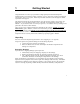
Getting Started 1 1 Congratulations! You have just purchased a high-quality thermal demand printer manufactured by the industry leader in quality, service, and value–Zebra Technologies Corporation. For over 25 years, Zebra has provided customers with the highest caliber of products and support. This manual provides all of the information you will need to operate your printer on a daily basis.
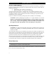
Getting Started Storage and Reshipping If you are not placing the Zebra Stripe Printer into operation immediately, repackage it using the original packing materials. The Zebra Stripe Printer may be stored under the following conditions. • Temperature: -40° to 140° F (-20 to 60° C) • Relative humidity: 5% to 85% non-condensing To ship the Zebra Stripe Printer, carefully pack it in a suitable container to avoid damage during transit. Whenever possible, use the original container from the factory.
Getting Started Voltage Selection 1 The Stripe is available from the factory preset for either 100-120 VAC electrical power or 220-240 VAC electrical power. Refer to the product label on the back of the printer and make sure that the unit is properly configured for your power requirements. AC Power Cable The AC Power Cable has a three-prong female connector on one end. See Figure 2. This connector must be plugged into the mating connector on the left side of the printer. See Figure 1.
Getting Started Communications The Stripe comes with either an Electronics Industries Association (EIA) RS-232 serial data interface or a factory-installed parallel interface. In both cases, you must supply the required interface cable for your application. See the Appendix for specific cable requirements. CAUTION: Zebra printers comply with FCC “ Rules and Regulations” , Part 15, Subpart J, for Class A Equipment, using fully shielded six-foot data cables.
Getting Started RIBBON SUPPLY OPEN PRINTHEAD SHOWN OPEN 1 RIBBON RELEASE BUTTON HEAD OPEN LEVER MEDIA SUPPLY PRINTHEAD ASSEMBLY MEDIA SUPPLY GUIDE MEDIA SENSOR ASSEMBLY MEDIA GUIDE MEDIA SUPPLY HANGER Figure 3 Roll Media Loading in Tear-Off Mode Media and Ribbon Loading Media NOTE: A Media Calibration must be performed when media and ribbon (if used) are first installed in the printer, or when a different type of media or ribbon is installed. See page 14.
Getting Started Fanfold Media Loading Fanfold media, from outside the printer, feeds through either the bottom or rear access slot. To load fanfold media, thread the media through the Printhead Assembly as shown in Figure 4. Adjust the Media Supply Guide and the Media Guide against the outer edge of the media. These Guides must not cause pressure or excessive drag on the media. CLOSE the Head Open Lever, and see page 10 to adjust the Media Sensor position.
1 Getting Started Figure 4 Fanfold Media Loading in Tear-Off Mode Figure 5 Cutter Mode Media Loading 7
Getting Started Peel-Off Mode Media Loading (Peel-Off Option Required) Figure 6 illustrates an S-500 printer with the Peel-Off Option. To insure proper media loading, see Figure 6 and follow the procedure below. 1. Slide the Media Supply Guide, Media Guide, and the Outer Edge Guides on both the Platen Guide Rod and the Lower Guide Rod as far out from the Printer Frame as possible. 2. Open the Head Open Lever and raise the Printhead Assembly. 3. Remove the Hold Down Hook. 4.
1 Getting Started Figure 6 Peel-Off Mode Media Loading Removing the Label Backing Material (Peel Off Option Required) When the amount of backing wound on the Backing Rewind Spindle reaches full capacity, the Backing Rewind Spindle Full Sensor activates, the Paper/Ribbon light flashes, and printing pauses. To remove the backing material, follow these steps (you don’t need to turn the printer Power OFF for this procedure): 1. 2. 3. 4.
Getting Started Adjusting the Media Sensor When the Stripe printer is powered ON, it performs a self test and configures its operating characteristics. Some of these characteristics are determined by the position of the Media Sensor. See Figure 7. The Media Sensor Assembly consists of two sections. The media passes between a stationary light source and a movable light sensor. The light source is positioned below the media, while the light sensor is positioned above the media.
Getting Started Ribbon Loading 1 Adjusting the Ribbon Supply Spindle Ribbon Supply Spindle: Normal Position In the Normal Position, the “ Dual-Tension” Ribbon Supply Spindle provides the desired amount of ribbon back-tension for different ribbon widths. To place the Spindle in the Normal Position, firmly pull the Spindle End-Cap until it clicks into place, as shown in Figure 8. Ribbon Supply Spindle: Low-Tension Position Low-Tension Position is used in limited applications with ribbons wider than 2.
Getting Started Figure 9 Ribbon Loading Diagram Loading the Ribbon To load ribbon, see Figure 9 and follow the procedure below. Note: Use ribbon that is wider than the media. The smooth backing of the ribbon protects the printhead from wear and premature failure due to excessive abrasion. For Direct Thermal Print Method, ribbon is not used and should not be loaded in the printer when performing the Media Calibration. 1. 2. 3. 4. 5. 6. Adjust the Ribbon Supply Spindle position for normal or low tension.
Getting Started Initial Printer Test 1 To insure proper sensing of the media and ribbon, perform a Media Calibration. This procedure establishes the media parameters for the printer. If loading the printer with media and ribbon for the first time, or changing the type of media, perform the Media Calibration on page 14.
Getting Started Configuration Mode The Configuration Mode allows you to fine-tune the internal printer configuration settings for your application.
Getting Started 4. 5. 6. 7. Turn the power switch ON. When the Power ON Self Test is complete, the POWER and PAUSE lights will be ON and the PRINTHEAD light will FLASH. Press the MODE key 3 times briefly. PAUSE and CALIBRATE lights turn ON. Close the Head Open Lever. Press UP to calibrate. The printer feeds some media. The MODE lights will flash ON and OFF to indicate that the settings have been saved in memory. Press PAUSE to exit the PAUSE mode. The PAUSE light turns OFF. 1 3.
Getting Started 16
2 Operation Now that your printer is ready for operation, how does it work? The Zebra Stripe Printer is designed to receive instructions from a host computer, such as an IBM-compatible PC. To create a label, you will either need to write a format in ZPL II, which is a programming language for creating label formats, or you will need to use a software program designed to format labels for the Zebra Stripe Printer.
Operation printing. The PAPER/RIBBON light flashes to indicate this condition. To remove the backing from the Rewind Spindle, see page 9. Cutter Mode (Factory-Installed Cutter Option Required) When the media is in the rest (idle) position, the start of the label to be printed is directly under the printhead. The printer prints the entire label and automatically cuts the label after it is printed. The Cutter Catch Tray “ catches” the completed labels.
2 Operation Figure 11 AC Power ON/OFF Switch Figure 12 Zebra Stripe Printer Front Panel 19
Operation Front Panel Keys PAUSE Key Starts and stops the printing process. - If the printer is not printing: no printing can occur - Printing: printing stops once the current label is complete FEED Key Forces the printer to feed one blank label. - Printer not printing: one blank label feeds immediately - Printing: one blank label feeds after the current batch of labels is complete CANCEL Key When in the PAUSE mode, this key will cancel print jobs.
Operation Printer Status Sensors The Zebra Stripe Printer contains several status sensors. These sensors alert the operator to various conditions by either stopping the printing or turning on a light. Sensor What it monitors How it works Checks the open/closed status of the Printhead lever. If the printhead is open, the Printhead Light flashes. Media Sensor Checks for proper media loading. If you run out of paper, the Paper/Ribbon Light will turn ON. (See Chapter 1 to adjust this sensor.
Operation Figure 14 Backing Rewind Spindle Full Sensor Position Figure 15 Label Available Sensor Position 22
Operation Sample ZPL II Label Formats This section contains three sample label formats for you to begin experimenting with. It is not intended as an introduction to ZPL II. To learn about ZPL II, send in the request card at the beginning of this book for a free copy of the ZPL II Programming Guide. For each format, do the following: 1. 2. Save the file. Copy the file to the printer. • Set-up the printer and turn the Power ON.
Operation Format 2: Saving a Label Format As a Graphic Image Line # Type this label format: 1 2 3 4 5 6 ^XA ^LH30,30 ^FO20,10^AD^FDZEBRA^FS ^FO20,60^B3N,Y,20,N^FDAAA001^FS ^ISFORMAT2,N ^XZ 7 8 9 ^XA ^ILFORMAT2 ^XZ You’ll get this printout: (Same as Format 1, but this format was also saved in the printer’s memory as a graphic image named “FORMAT2".) Line #1-4: These commands were described in Format 1.
3 Routine Care and Adjustment Cleaning CAUTION: Use only the cleaning agents indicated below. Zebra Technologies Corporation will not be responsible for any other fluids being used on this printer. No lubricants are needed. 3 Table 1 provides a brief cleaning schedule. Specific cleaning procedures are provided on the following pages.A Preventive Maintenance Kit (part # 01429) is available from Zebra. Kit items are also sold separately by the part numbers shown.
Routine Care and Adjustment Cleaning the Printhead Inconsistent print quality, such as voids in the bar code or graphics, may indicate a dirty printhead. For optimum performance, Zebra recommends performing the following cleaning procedure after every roll of ribbon. NOTE: It is not necessary to turn the printer OFF before cleaning the printhead. If power is turned OFF, all label formats and images, as well as any temporarily saved parameter settings stored in the printer’s internal memory, will be lost.
Routine Care and Adjustment Cleaning the Cutter Module (For Printers Equipped with the Optional Cutter) The Cutter Module requires periodic cleaning to remove paper dust and gummed label residue. The procedure on the following pages should be performed by the operator according to the schedule on page 25. However, depending on your application and media type you may need to clean the cutter more or less frequently. NOTE: In the figures shown, media and ribbon have been removed for clarity.
Routine Care and Adjustment I. Remove the Cutter Module from the printer. 1. Turn the printer’s AC power OFF. 2. Raise the printer’s Media Access Door and lower the printer’s Front Door. See Figure 17. 3. Remove the Label Catch Tray by lifting it up and away from the front of the Cutter Module. 4. See Figure 18. Gently pull straight down on the Cutter Cable Connector to remove it from the mating socket on the Cutter Module. 5.
3 Routine Care and Adjustment Figure 20 Cutter Module Disassembly II. Disassemble the Cutter Module. 1. See Figure 20. Hold the Cutter Module as illustrated. Put your thumbs on the two Wire Spring Loops and your index fingers on the top of the Rear Cutter Blade Guard. It may help to lay the Cutter Module on a table or other surface throughout this process. 2. To remove the Rear Cutter Blade Guard, first press down simultaneously on the two Wire Spring Loops.
Routine Care and Adjustment IV. Reassemble the Cutter Module. 1. See Figure 22. Position the two Wire Springs down against the Lower Cutter Blade. 2. Place the Rear Cutter Blade Guard over the Wire Springs, perpendicular to its final position. Place your thumbs on the top (flat) part of the Guard. NOTE: Insure that the ends of the Rear Cutter Blade Guard are positioned on the outside of the Cutter Side Panels. 3. See Figure 22.
3 Routine Care and Adjustment Figure 23 Reassembled Cutter Module Figure 24 Cutter Module Reinstallation 31
Routine Care and Adjustment V. Reinstall the Cutter Module. 1. See Figure 19. Position the Cutter Module above the Cutter Mounting Posts. Press down on the Cutter Module until the Mounting Slots engage the Mounting Posts on the printer. 2. See Figure 18. Tighten the Mounting Screw in a clockwise direction to hold the Cutter Module in Position. 3. See Figure 18.
Routine Care and Adjustment Mechanical Adjustments The Stripe printer has been designed with minimal operator adjustments required. Print Quality Adjustments In the factory, the Stripe printer is aligned and tested using Zebra’s 5319 ribbon and Zebra’s Z-Trans 6A full width, non-continuous media to print thermal transfer labels at Speed C (4"/sec). For other media/ribbon combinations, the user may need to adjust Print Darkness, Toggle Pressure, or possibly the Printhead Position.
Routine Care and Adjustment Toggle Pressure Adjustment The Toggle Assembly presses the printhead against the ribbon (if used), the media, and the platen. The pressure applied by the Toggle Assembly may need to be increased or reduced when different thicknesses or widths of media are used in the printer. Before increasing Toggle Pressure to achieve darker print darkness, perform the Print Quality Adjustments on page 33. Turn the two knurled knobs on top of the Toggle Assembly to adjust the pressure.
Routine Care and Adjustment Media Sensor Position Adjustment This procedure was covered in Chapter 1. See page 10. Ribbon Supply Spindle Adjustment This procedure was covered in Chapter 1. See page 11. Backing Rewind Power Roller Adjustment (Peel-Off Option Required) NOTE: This Roller is only present on printers with the Peel-Off Option. Zebra presets this Roller during manufacture for proper operation with most applications. Only adjust this Roller when necessary.
Routine Care and Adjustment When the Power Roller is properly adjusted, the backing material should have even tension across its entire width and be wrapped snugly around all Guides and Rollers. If the tension is not even, the media/backing material may slide (walk) to the left or to the right as printing occurs. This can cause print registration problems on the labels. Figure 26 illustrates an improperly adjusted Backing Rewind Power Roller.
4 Troubleshooting and Diagnostics If the Zebra Stripe Printer operates in an abnormal fashion, consult the Troubleshooting Table below. The Printer Diagnostics following the Troubleshooting Table may also help you to determine the problem. The troubleshooting of some problems may be beyond the abilities of the operator. In these cases, call a service technician to perform additional troubleshooting and repair procedures.
Troubleshooting and Diagnostics Troubleshooting Table Symptom Diagnosis Action Printer stops, PAUSE light ON and PAPER/ RIBBON light FLASHING. Ribbon incorrectly or not loaded. Load ribbon correctly. See Chapter 1. Malfunctioning Ribbon Sensor. Call a service technician. Printer stops, PAUSE light ON and PRINTHEAD light FLASHING. Printhead is not fully closed. Close printhead completely. Printhead Open Sensor not detecting its position flag. Call a service technician. Printer stops.
Troubleshooting and Diagnostics Troubleshooting Table Diagnosis Action Truncated print, no print, or FEED Key operates incorrectly while using non-continuous media. Media or ribbon improperly loaded. See Media and Ribbon Loading Instructions in Chapter 1. Incorrect Media Sensor Position or Sensitivity. See Media Sensor Position Adjustment in Chapter 1. In Peel-Off Mode, skewed or stuck labels. Glue material from Back of Labels causing media movement problems.
Troubleshooting and Diagnostics Troubleshooting Table Symptom Diagnosis Action When using wide ribbon (over 2.4"), the image gets lighter or smears near the end of the roll of ribbon. Ribbon appears to slow down or stop. Too much back-tension on the ribbon. See Chapter 1. Adjust the Ribbon Supply Spindle to provide low tension. ZPL was sent to printer, but not recognized. The DATA light remains OFF Communications parameters or DIP Switches are set incorrectly. Perform the MODE Key Self Test.
Troubleshooting and Diagnostics Troubleshooting Table Symptom Printing stops. PAPER/RIBBON, PAUSE, and CANCEL lights on For printers with the Cutter Option installed. Diagnosis Action Out of media. Load media. See Chapter 1. Media jammed in Cutter. Remove media, clean Cutter Module if necessary. See page 27. Connecting cable not connected to Cutter Module. Plug Cable into Cutter Module. See page 27. Cutter Module is dirty. Clean Cutter Module. See page 27.
Troubleshooting and Diagnostics CANCEL Key Self Test This self test prints the printer’s configuration parameters that are currently stored in Configuration (EEPROM) Memory. See Figure 27. The configuration may be changed either temporarily (for specific label formats or ribbon and label stock), or permanently (by saving the new parameters in memory.) Saving new parameters occurs whenever a Printer Configuration procedure is performed. See Chapter 1 for more information.
Troubleshooting and Diagnostics FEED Key Self Test The results of this self test will be used to determine the best Darkness Setting for a specific media/ribbon combination. See Figure 29. The FEED Key Self Test labels will print at various plus or minus Darkness settings relative to the current darkness setting. The operator inspects these printouts and determines which printout has the best darkness setting.
Troubleshooting and Diagnostics MODE Key Self Test This self test places the printer in a Communications Diagnostics Mode. In this mode, the printer prints the ASCII characters and their corresponding hexadecimal values for any data received from the host computer. See Figure 30. Note: Turn the power OFF to exit this self test. FEED Key and PAUSE Key If it is ever necessary to reset the printer configuration to the factory default values, press these two keys at the same time while turning the Power ON.
5 Specifications Note: Your printer may not have all of the options described in these specifications. General Specifications Height 13" 330mm Width 8.25" 209.6mm Depth 17" 431.8mm Weight (option-dependent) 17.25 lbs 72.21 kg Electrical 110 or 220 VAC +10%/ 15%, 48-62 Hz − 5 Amps @ 110V, 3 Amps @ 220V Built to CISPR 22B, UL 1950, CSA 950, IEC 950, 801-2,-3, and -4 standards; Complies with FCC class A and Canadian Doc.
S p e c i f i ca t i o n s Media Specifications Total media width Maximum Label length 4.5" 115 mm Maximum with cutter installed 4.0" 101.6 mm Minimum 0.75" 19 mm Maximum See Printing Considerations (page 45) Minimum Tear-Off 0.63" 16 mm Peel-Off 1.00" 25.4 mm Cutter 1.50" 38.1 mm 0.012" 0.304 mm 0.003" 0.076 mm Total thickness Maximum (Printhead position (includes liner) may need to be adjusted above 0.01") Minimum Core size 3.0" 76.2 mm Maximum roll diameter 8.0" 203.
S p e c i f i ca t i o n s Options • • • • • • • (* Factory-Installed) 512 KB RAM Expansion (for a total of 1 MB RAM) (S-500 only) 256 KB RAM Expansion (for a total of 512 KB RAM) (S-300 only) * 256 KB Battery Backed-Up RAM for label formats and graphics (S-500 only) * Peel-Off Mode with Backing-Only Rewind feature (S-500 only) * Cutter with Label Catch Tray (S-500 only) Scalable and Bitmap Smooth Fonts available for text (S-500 only) Parallel interface (S-500 only) ® Zebra Programming Language (ZPL II
S p e c i f i ca t i o n s Standard Printer Fonts For more information on fonts, refer to your ZPL II Programming Guide. 8 Dots/mm Printhead Minimum Dot Matrix Fonts (h x w) Type* Character Size (h x w) (Defaults) Max Char /In A 9x5 U-L-D .044 11 x 7 U .054 22.7 C, D 18 x 10 U-L-D E 28 x 15 OCR-B F 26 x 13 U-L-D G 60 x 40 U-L-D H 21 x 13 OCR-A ″ x .030″ ″ x .044″ .089 ″ x .059″ .138 ″ x .098″ .128 ″ x .079″ .295 ″ x .236″ .103 ″ x .093″ 33.3 B GS 24 x 24 SYMBOL .118" x .
S p e c i f i ca t i o n s Standard Printer Font Examples Figure 31 Default Printer Fonts (8 Dots/mm) 5 Figure 32 Default Printer Fonts (6 Dots/mm) 49
S p e c i f i ca t i o n s Optional Printer Fonts There are many optional character fonts that can be purchased for your Stripe in addition to those which are standard in the unit. From time to time, additions may be made to the list of available fonts. Contact Zebra Technologies Corporation or your sales representative for further information. Only one additional font can be installed in the printer at a time. This installation should be performed by a service technician.
S p e c i f i ca t i o n s Optional Printer Font Examples CG Tr iumvirate - Standar d 0123456789.,?!AaBbCc CG Tr iumvirate - Itali c 0123456789.,?!AaBbCcDdEe CG Triumvirate - Bold 0123456789.,?!AaBbCcDd CG Triumvirate - Bold Italic 0123456789.,?!AaBb CG Times - Standard 0123456789.,?!AaBbCcDdEeFfGg CG Times - Bold 0123456789.,?!AaBbCcDdEeFfGgHh CG Times - Italic 0123456789.,?!AaBbCcDdEeFfGgHhIi CG Times - Bold Italic 0123456789.,?!AaBbCcDdEeFf - Standard 0123456789.
Specifications Figure 35 Bitmap Smooth Fonts: Point Size Examples 52
6 Support Services How to Reach Us Which number do you need? Zebra Technologies Corporation, USA Zebra Technologies Europe Limited, UK Inquiry Department: For literature and (847) 634-6700 distributor information. Customer Service: Printers, parts, media, and ribbon: call your distributor or (847) 634-6700 call Zebra Technologies Corporation.
Support Services Technical Support Service via Telephone Before you call - Misunderstanding instructions or omitting a step are the most common sources of error. Please reread the manual and use the table of contents and appendixes for help. Be prepared - To possibly avoid excess time and expense of a long-distance phone call, please complete the Service Form on the next page in its entirety. Only with ALL of the information requested can we give you accurate and fast assistance.
Support Services Zebra Technologies Corporation Service Form Zebra Technologies Corporation 333 Corporate Woods Parkway Vernon Hills, Illinois 60061-3109 Zebra Technologies Europe Limited Zebra House, The Valley Centre Gordon Road, High Wycombe Buckinghamshire HP13 6EQ England Phone Number: (847) 913-2259 Telefax Number:(847) 913-2578 Phone Number: +44 (0) 1494 472872 Telefax Number: +44 (0) 1494 450103 Complete this form before requesting technical assistance.
Support Services Product Service and Support Programs At Zebra Technologies, our service and support goal is to keep your printer performing optimally. Zebra Technical and Repair Services provide a broad range of service options and are your expert sources for your support and maintenance needs. If you are in need of technical assistance or repair services, our technical support staff stands ready with answers to any questions you may have.
Support Services Wang Customer Services Division Zebra Technologies’ Authorized National Service Supplier provides On-Site Maintenance of the complete line of Zebra printers. Wang and Zebra work together to provide the TotalCare Service Program for our customers. TotalCare is a comprehensive package of support services designed specifically for the Zebra line of printer products. Your business requires the Zebra printer to be ready when you are.
Support Services and training. Take advantage of our years of experience and give your technicians the advantage of comprehensive factory training. Training is conducted at Zebra’s Corporate facility located a short drive away from Chicago’s O’Hare International airport. A full range of subjects are offered from basic indoctrination through maintenance and adjustments to advanced programming techniques. On-site training and custom classes are available.
Support Services Zebra Training Programs At Zebra Technologies, our training goal is to provide quality training programs that enhance the value of your Zebra® printers. We realize two of the most important aspects of successful printer operation and maintenance are experience and training. Now you can take advantage of our years of experience in operations, applications, maintenance and technical support and give yourself the advantage of comprehensive factory training.
Support Services Operations and Maintenance Courses Each Operations and Maintenance Course first introduces the student to various bar code concepts and terminology. Topics include direct thermal/thermal transfer printing, continuous and non-continuous media, thin film thermal printheads, and serial and parallel communication interfaces. After completing this introductory material, the student focuses on printer setup and configuration.
Support Services Bar Codes at Work This one day course presents an introduction to Bar Coding. This course will discuss bar code terminology, specifications, and applications associated with selected, often-used bar codes. In order to gain a better understanding of labeling problems and solutions, the selection and matching of media and ribbons with be discussed.
Support Services 62
Appendix Adjusting the Printhead Only adjust the printhead position if you have done the following and are still experiencing unsatisfactory print quality (the procedures for these adjustments are located in Chapter 3.): 1. 2. 3. Check the initial print quality. Adjust the print darkness. Adjust the toggle pressure. Printhead Position Adjustment Procedure Refer to Figure 36 throughout this procedure. You will need a #2 Phillips screwdriver, a 2.5 mm Hex (Allen Key) Driver, and a flathead screwdriver. 1.
Appendix Figure 36 Print Quality Adjustment 15. Re-install the Printhead Support Bracket using the two mounting screws. 16. Press PAUSE and observe the test labels to insure consistent print quality and proper parallelism across the top of the labels. Repeat procedure if required. 17.
Appendix Printer Interface Technical Information RS-232 Interface Signal Levels For all RS-232 input and output signals, the Stripe printer follows both the Electronics Industries Association (EIA) RS-232 and the Consultative Committee for International Telegraph and Telephone (CCITT) V.24 standard signal level specifications. RS-232 Connector Pinout Pin No.
Appendix RS-232 Cabling Requirements The required cable must have a 25-pin “ D” Type (DB25P) connector on one end, which is plugged into the mating (DB25S) connector located inside the access opening on the left side of the printer. (Refer to Figure 11 on page 19 for the location of this cable.) The other end of the Signal Interface Cable connects to an appropriate point at the host computer. This cable will be one of two types–standard or null modem–depending on the specific interface requirements.
Appendix Parallel Interface The parallel interface provides a means of communication which is typically faster than the previously mentioned serial interface method. In this method, the bits of data which make up a character are sent all at one time over several wires in the cable, one bit per wire. Data signals are defined as either HIGH or LOW while control signals are either Active or Inactive. This distinction is due to the fact that some Control Signals are active HI while others are active LOW.
Appendix Signal Descriptions The following chart provides a description of each of the pins in the parallel connector. A standard parallel data cable will provide the required interconnection between the computer and the Stripe printer. Pin No. Parallel Connector Pinout 1 The STROBE printer input has internal 3.3K pull-up resistors to 5V (IOL= 1.5mA) and is designed to receive a signal driven open collector VOL <= 0.8V. This pin is a signal from the host computer.
alphanumeric Indicating letters, numerals, and characters such as punctuation marks. backfeed Backfeed is when the printer pulls the media and ribbon (if used) backward into the printer so that the beginning of the label to be printed is properly positioned behind the printhead. Backfeed occurs when you’re operating the printer in tear-off, peel-off, or cutter mode. bar code A code by which alphanumeric characters can be represented by a series of adjacent stripes of different widths.
Glossary recycled by the end-users. Label backing (or liner) has a non-stick surface which allows the label to be easily removed by the end-user and placed in the desired location. media Material onto which data is printed by the printer. Types of media include: tagstock, continuous, fanfold, roll, etc. media sensor This sensor is located behind the printhead to detect the presence of media and, for non-continuous media, the position of the web, hole, or notch that separates each label.
Index A AC Power, 3, 18 AC Power Cable, 3 AC Power Fuse, 32 Adjustments Media Sensor Position, 10, 33, 35 Print darkness, 33 Print Quality, 33 Printhead Position, 33, 63 Backing Rewind Power Roller Adjustment, 35 Toggle Pressure, 33-34 ASCII Control Codes XOFF (DC3), 67 XON (DC1), 67 B Baud Rate, 13 C CANCEL Key, 20 Caution Shipping, 2 Unshielded Cables, 4 Ventilation, 2 CCITT V.
Index Media Calibration, 14 Media Guide, 5 Media Sensors, 10, 26 Media Supply Guide, 5 MODE Key, 20 N Null Modem, 67 O Operating Modes Cutter, 18 Peel-Off, 17 Rewind (External), 6, 18 Tear-Off, 5, 17 Operator Controls, 46 Option Switches, 13 Optional Fonts, 50 P S Self Tests CANCEL Key, 42 FEED Key, 43 FEED Key and PAUSE Key, 44 MODE Key, 44 PAUSE Key, 42 Power ON, 41 Serial Communication Port, 67 Shipping Container, 2 Shipping Damage, 1 Signal Ground, 66 Specifications, 45 Standard Fonts, 48 Storage an