
User Manual

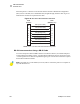


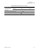
Table Of Contents
- Table of Contents
- Proprietary Statement
- Declaration of Conformity
- Warranty Information
- Preface
- Introduction
- Printer Setup
- Printer Operation
- Configuration
- RFID Guidelines
- Routine Care and Adjustments
- Troubleshooting
- Data Connections
- Specifications
- Index

Data Connections
Serial Data Port
R4Mplus User Guide 105
RS-232 Interface Connections
The printer is configured as Data Terminal Equipment (DTE). Figure 37 shows the internal
connections of the printer’s RS-232 connector.
Figure 37 • RS-232 Internal Connections
7 RTS Request to send—output from printer
8 CTS Clear to send—input to printer
*9 +5 V DC +5 VDC
* This pin is also available as a +5 VDC power source at 750 mA. To enable this capability, a jumper on the computer’s
main logic board needs to be installed on JP1, pins 2 and 3.
Note • An interface module is required for RS-422/RS-485 interface support
(refer to page 107).
Note • You must use a a null modem (crossover) cable to connect the printer to a computer or
any other DTE devices.
Table 18 • Serial Data Connector Pin Configuration (Continued)
Pin Number Name Description
1
(TD)
(TD)
(RD) (RD)
(RTS) (RTS)
(DSR) (DSR)
(SG) (SG)
(DTR) (DTR)
DTE DTE
1
22
33
44
55
66
77
88
99