5 RFID Guidelines This chapter provides an overview of how RFID works and the ZPL commands used to create RFID labels. Contents Overview . . . . . . . . . . . . . . . . . . . . . . . . . . . . . . . . . . . . . . . . . . . . . . . . . . . . . . . . . . . . . Transponder Placement. . . . . . . . . . . . . . . . . . . . . . . . . . . . . . . . . . . . . . . . . . . . . . . . . . ZPL II Commands for RFID . . . . . . . . . . . . . . . . . . . . . . . . . . . . . . . . . . . . . . . . . . . . . . .
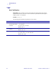
RFID Guidelines Overview Overview The R110XiIIIplus “smart” label printer-encoders serve as dynamic tools for both printing and encoding RFID labels, tickets, and tags. The printer encodes information on ultra-thin UHF RFID transponders embedded in “smart” labels. It then immediately verifies proper encoding and prints bar codes, graphics, and/or text on the label’s surface. For more information about RFID media, see RFID “Smart” Labels on page 16.
RFID Guidelines ZPL II Commands for RFID ZPL II Commands for RFID Printing and encoding (writing) of “smart” labels is handled through the use of Zebra Programming Language (ZPL). Each transponder has memory that can be read from through ZPL commands, and most transponders have memory that can be written to. The printer divides the ZPL commands that it receives into two categories: RFID and non-RFID (such as the printing commands for bar codes or human-readable text). The RFID commands are executed first.
RFID Guidelines ^HV ^HV Host Verification Description This command is used to return data from specified fields, along with an optional ASCII header, to the host. It can be used with any field that has been assigned a number with the ^RT command. Format ^HV#,n,h The following table identifies the parameters for this format. Parameters Details # = field number The value assigned to this parameter should be the same as the one used in the specified with another ^RT command.
RFID Guidelines ^RS ^RS RFID Setup Important • Use care when using this command in combination with ^RT (reading tag data). Problems can occur if the data read from the tag is going to be printed on the label. Any data read from the transponder must be positioned to be printed above the read/write position. Failure to do this will prevent read data from being printed on the label.
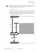
RFID Guidelines ^RS Example 1 • This example sets the printer to move the media to 800 dots from the top of the media [or label length minus 800 from the bottom (leading edge) of the media] and voids the rest of the media in case of an error. The printer will try to print two labels, then will pause the printer if printing and encoding fail. ^XA ^RS,800,,2,P^FS ^XZ The following illustration shows the resulting voided label. Note where the void starts.
RFID Guidelines ^RS Example 2 • This example sets the printer to move the media to 800 dots from the top of the media [or label length - 500 from the bottom (leading edge) of the media] and prints “void” 500 dots in vertical length (Y axis) in case of an error. ^XA ^RS,800,500,2,P^FS ^XZ The following illustration shows the resulting voided label. Note where the void starts.
RFID Guidelines ^RT ^RT Read Tag Description The ^RT command tells the printer to read the current RFID tag data. The data can be sent back to the host via the ^HV command. Format ^RT#,b,n,f,r,m,s The following table identifies the parameters for this format. Parameters Details # = number to be assigned to the field Accepted values: 0 to 9999 Default value: 0 Accepted values: 0 to n, where n is the maximum number of blocks for the tag.
RFID Guidelines ^WT ^WT Write Tag Note • Check the amount of data memory available for the tag that you will be using. If more is sent than the memory can hold, the data will be truncated. Description The ^WT command allows you to program the current RFID tag. Format ^WTb,r,m,w,f,v The following table identifies the parameters for this format.
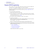
RFID Guidelines Sample of RFID Programming Sample of RFID Programming ZPL II is Zebra’s label design language. ZPL II lets you create a wide variety of labels from the simple to the very complex, including text, bar codes, and graphics. This section is not intended as an introduction to ZPL II. If you are a new ZPL II user, order the ZPL II Programming Guide (part number 46530L) or go to http://support.zebra.com to download the guide. For your programming, do the following: 1.
RFID Guidelines Sample of RFID Programming Table 7 • Sample ZPL Code and Results Line Number Type This Label Format Resulting Printout 1 ^XA 2 ^RS,0^FS ZEBRA 5A65627261000000 3 ^WT^FDZebra^FS 4 ^FO100,100^A0n,60^FN0^FS 5 ^FO100,200^A0n,40^FN1^FS 6 ^RT0^FS 7 ^RT1,,,1^FS 8 ^XZ Line 1 Indicates start of label format. Line 2 Indicates no movement for media. Line 3 Writes the data “Zebra” to the tag. Line 4 Print field number ‘0’ at location 100,100.
RFID Guidelines Sample of RFID Programming Notes • ___________________________________________________________________ __________________________________________________________________________ __________________________________________________________________________ __________________________________________________________________________ __________________________________________________________________________ __________________________________________________________________________ ________________
6 Data Ports This chapter describes the standard communication ports available to connect the printer to your computer or network. Contents Parallel Port . . . . . . . . . . . . . . . . . . . . . . . . . . . . . . . . . . . . . . . . . . . . . . . . . . . . . . . . . . . Serial Port . . . . . . . . . . . . . . . . . . . . . . . . . . . . . . . . . . . . . . . . . . . . . . . . . . . . . . . . . . . . Serial Pin Configuration . . . . . . . . . . . . . . . . . . . . . . . . . . . . . . . . . . . . . . . . .
Data Ports Parallel Port Parallel Port When communicating via the parallel port, the values selected must be the same as those used by the host equipment connected to the printer. Port selection for status information is determined by the channel sending the request. The parallel port can be set for bidirectional or unidirectional communication. The default setting is bidirectional. A standard 36-pin parallel connector (Figure 30) is available on the back of the printer for connection to the data source.
Data Ports Parallel Port Table 8 • Parallel Cable Pin Configuration (Continued) 36-Pin Connectors 18 19–30 6/7/2004 +5 V at 750 mA The maximum current draw may be limited by option configuration. Ground 31 ninit 32 nFault/NDataAvail 33, 34 23063L-001 Rev. 1 Description Not used 35 +5 V through a 1.
Data Ports Serial Port Serial Port To communicate using the serial data port of the printer, you must choose the number of data and stop bits, parity, and handshaking. Parity applies only to data transmitted by the printer because the parity of received data is ignored. The values selected must be the same as those used by the host equipment connected to the printer. Default settings are 9600 baud, 8 data bits, 1 stop bit, no parity, and XON/XOFF.
Data Ports Serial Port Serial Pin Configuration Table 9 shows the pin configuration and function of the rear panel serial data connector on the printer. Table 9 • Serial Connector Pin Configuration \ 23063L-001 Rev. 1 Pin No.
Data Ports Serial Port RS-232 Interface Connections Note • Adapters are available from Zebra Technologies LLC. • RS-422/RS-485 adapter, Zebra part number 33114M • RS-232 DB-9 to DB-25 adapter, Zebra part number 33109M Direct Connection to a Computer The printer is configured as Data Terminal Equipment (DTE). Note • Use a null modem (crossover) cable to connect the printer to a computer or any other DTE device. Figure 32 shows the internal connections of the printer’s RS-232 connector.
Data Ports Serial Port DB-9 to DB-25 Connections An interface adapter is required (Zebra part number 33109M) to connect the printer’s DB-9 interface to a DB-25 connector. A generic DB-25 adapter CAN be used, although the +5 VDC signal source would not be passed through the adapter. Figure 33 shows the connections required for the DB-9 to DB-25 interface.
Data Ports Serial Port RS-422/RS-485 Interconnections Caution • A qualified service technician must install a jumper on the printer’s main logic board at JP1, pins 2 and 3, for the RS-422/RS-485 interface adapter to function properly. An interface adapter (Zebra part number 33114M) is required to connect the printer’s RS-232 DB-9 interface to a host computer through an RS-422 or RS-485 interface. A generic DB-25 adapter can be used.
Data Ports USB 2.0 Port USB 2.0 Port A USB 2.0 port (which is USB 1.1 and 1.0 compatible) is available to connect your printer to the host equipment. The industry-standard USB cable has an A-male connector on one end and a B-male connector on the other end as shown in Figure 36. Figure 36 • USB Connectors = 16.4 ft (5 m) maximum Note • Use a USB 2.0-certified compliant cable no longer than 16.4 ft (5 m) long. A cable that meets these requirements is available from Zebra (part number 33011).
Data Ports USB 2.
7 Memory Cards This chapter describes the optional cards that can be used with the printer and gives instructions for installation. Contents PCMCIA Memory Card . . . . . . . . . . . . . . . . . . . . . . . . . . . . . . . . . . . . . . . . . . . . . . . . . . 84 CompactFlash Card . . . . . . . . . . . . . . . . . . . . . . . . . . . . . . . . . . . . . . . . . . . . . . . . . . . . . 86 23063L-001 Rev.
Memory Cards PCMCIA Memory Card PCMCIA Memory Card A Type 1- or Type II-compliant PCMCIA memory card holds extra memory or font options for the printer. The card is hot-swappable (it can be installed while the printer is on). Electrostatic Discharge Caution • Observe proper electrostatic safety precautions when handling any static-sensitive components such as circuit boards and printheads. To install the PCMCIA card, complete these steps: 1.
Memory Cards PCMCIA Memory Card 3. Reinstall the PCMCIA card shield over the PCMCIA card and card slot. Note • The PCMCIA card may take a few minutes to initialize. The PAUSE light flashes while the card initializes. If the card is already initialized, the PAUSE light flashes only once or twice after the card is installed. The printer is ready to operate with the additional memory or font option.
Memory Cards CompactFlash Card CompactFlash Card A CompactFlash card is a nonvolatile memory card that stores data even when the power to the printer is turned off. A Type I-compliant CompactFlash card holds extra memory or optional fonts for your printer. Caution • This procedure should only be performed by qualified service technicians. Electrostatic Discharge Caution • Observe proper electrostatic safety precautions when handling any static-sensitive components such as circuit boards and printheads.
Memory Cards CompactFlash Card 5. Insert the CompactFlash card into the card slot on the upper portion of the option board. Insert the card with the back (unlabeled) side of the card facing out. The card can be inserted only one way and should snap into place. Figure 39 shows where to insert the CompactFlash card. Figure 39 • Compact Flash Card Insertion 1 1 2 3 2 3 Option board Card slot Compact flash card 6.
Memory Cards CompactFlash Card Notes • ___________________________________________________________________ __________________________________________________________________________ __________________________________________________________________________ __________________________________________________________________________ __________________________________________________________________________ __________________________________________________________________________ ____________________________
8 Routine Maintenance Cleaning your printer regularly maintains print quality and may extend the life of the printer. This section provides routine cleaning and maintenance procedures. Contents Cleaning Schedule . . . . . . . . . . . . . . . . . . . . . . . . . . . . . . . . . . . . . . . . . . . . . . . . . . . . . . Clean Exterior . . . . . . . . . . . . . . . . . . . . . . . . . . . . . . . . . . . . . . . . . . . . . . . . . . . . . . . . . Clean Interior . . . . . . . . . . . . . . . . . . . . . . .
Routine Maintenance Cleaning Schedule Cleaning Schedule The recommended cleaning schedule is shown in Table 10. See the following pages for specific procedures. Caution • Use only the cleaning agents indicated. Zebra is not responsible for damage caused by any other fluids being used on this printer.
Routine Maintenance Clean Interior Clean Interior After every four rolls of media, inspect the inside of the printer. Use a soft bristle brush or a vacuum cleaner to remove any dirt and lint from the interior of the printer. Printhead and Platen Roller After every roll of ribbon, clean the printhead. Clean the printhead more often if you see inconsistent print quality, such as voids in the bar code or graphics.
Routine Maintenance Clean Interior Figure 40 • Cleaning the Printhead 3 4 1 2 1 2 3 4 Applicator Platen roller Printhead print elements Printhead lever 4. Rotate the platen roller and clean thoroughly with solvent and an applicator. 5. Brush or vacuum any accumulated paper lint and dust away from the rollers. 6. Reload the media and the ribbon (if required). 7. Close the printhead. 92 RXiIIIPlus User Guide 6/7/2004 23063L-001 Rev.
Routine Maintenance Clean Interior Sensors Brush or vacuum any accumulated paper lint and dust off the sensors whenever the sensors are blocked. At minimum, clean the sensors according to the recommendations in Cleaning Schedule on page 90. Ribbon and Label-Available Sensor Locations The ribbon sensor and optional label-available sensor are shown in Figure 41. Figure 41 • Sensor Locations 1 2 1 2 23063L-001 Rev.
Routine Maintenance Clean Interior Transmissive (Media) Sensor Locations The locations of the upper and lower transmissive (media) sensors are shown in Figure 42 and Figure 43. Figure 42 • Upper Media Sensor 1 1 Upper media sensor Figure 43 • Lower Media Sensor 1 1 94 Lower media sensor RXiIIIPlus User Guide 6/7/2004 23063L-001 Rev.
Routine Maintenance Clean Interior Snap Plate Clean the snap plate when label adhesive or a label is stuck to the underside. Figure 44 shows the location of the snap plate. Figure 44 • Snap Plate 1 6 5 4 1 2 3 4 5 6 2 3 Antenna support screws Location of right-side snap plate screw (screw not shown) Snap plate Antenna support Antenna support frame Left-side snap plate screw To clean the snap plate, complete these steps: 1.
Routine Maintenance Replace Fuse Replace Fuse The R110XiIIIPlus fuse must be replaced only by an authorized service technician. Caution • Turn the AC power switch Off (O) and remove the power cord before performing this procedure. The printer uses a metric-style fuse (5 × 20 mm IEC) rated at F5A, 250 V. The AC power entry module comes with two approved fuses in the fuse holder: one is in-circuit, and the second is provided as a spare.
Routine Maintenance Replace Fuse Figure 46 • Fuse Locations 1 2 3 1 2 3 In-circuit fuse Fuse holder Spare fuse 3. Snap the fuse holder back into the AC power entry module. 4. Reconnect the power cord, and turn the printer On (I). Note • If the printer does not power on, an internal component failure may have occurred, and the printer requires servicing by an authorized service technician. 23063L-001 Rev.
Routine Maintenance Replace Fuse Notes • ___________________________________________________________________ __________________________________________________________________________ __________________________________________________________________________ __________________________________________________________________________ __________________________________________________________________________ __________________________________________________________________________ __________________________
9 Troubleshooting This chapter provides you with information about LCD, print quality, communications, and other errors that you might need to troubleshoot. Contents Troubleshooting . . . . . . . . . . . . . . . . . . . . . . . . . . . . . . . . . . . . . . . . . . . . . . . . . . . . . . . LCD Error Messages . . . . . . . . . . . . . . . . . . . . . . . . . . . . . . . . . . . . . . . . . . . . . . . . . . . Print Quality Problems . . . . . . . . . . . . . . . . . . . . . . . . . . . . . . . . . . . . .
Troubleshooting Troubleshooting Troubleshooting If an error condition exists with the printer, review this checklist: Is there an error message on the LCD? If yes, see LCD Error Messages on page 101 for more information. Is the CHECK RIBBON light on when ribbon is loaded properly, or are non-continuous labels being treated as continuous labels? If yes, see Media and Ribbon Sensor Calibration on page 34. Are you experiencing problems with print quality? If yes, see Print Quality Problems on page 104.
Troubleshooting LCD Error Messages LCD Error Messages The LCD displays messages when there is an error. See Table 11 for LCD errors, the possible causes, and the recommended solutions. Table 11 • LCD Error Messages LCD Possible Cause Recommended Solution RIBBON OUT Thermal Transfer Mode— Load the ribbon correctly, following directions in Ribbon is not loaded or is loaded Load Ribbon on page 26. incorrectly. Thermal Transfer Mode— Adjust the media and ribbon sensors.
Troubleshooting LCD Error Messages Table 11 • LCD Error Messages (Continued) LCD Possible Cause Recommended Solution RIBBON IN Ribbon is loaded, but the printer • To operate in Direct Thermal mode, remove the is set for Direct Thermal mode. ribbon. • To operate in Thermal Transfer mode, leave the ribbon loaded and change the print method to Thermal Transfer. See Selecting Print Method on page 45. • Ensure that the printer driver and/or software settings are correctly set (if applicable).
Troubleshooting LCD Error Messages Table 11 • LCD Error Messages (Continued) LCD Possible Cause HEAD COLD Recommended Solution Caution • An improperly connected printhead data or power cable can cause this error message. The printhead can still be hot enough to cause severe burns. Allow the printhead to cool. The printhead is under temperature. Continue printing while the printhead reaches the correct operating temperature. If the error remains, the environment may be too cold for proper printing.
Troubleshooting Print Quality Problems Print Quality Problems Table 12 identifies problems with print quality, the possible causes, and the recommended solutions. Table 12 • Print Quality Problems Problem Possible Cause Recommended Solution General print quality You are using an incorrect Consult your authorized Zebra reseller or distributor issues combination of labels and ribbon for information and advice. for your application.
Troubleshooting Print Quality Problems Table 12 • Print Quality Problems (Continued) Problem Possible Cause Recommended Solution Light, consistent The printhead or platen roller is vertical lines running dirty. through the labels Clean the printhead and platen roller as instructed in Printhead and Platen Roller on page 91. Caution • The printhead is hot and can cause severe burns. Allow the printhead to cool.
Troubleshooting Communications Problems Communications Problems Table 13 identifies problems with communications, the possible causes, and the recommended solutions. Table 13 • Communications Problems Problem Possible Cause A label format was sent to The communication the printer but was not parameters are incorrect. recognized. The DATA light does not flash. Recommended Solution Check the printer driver or software communications settings (if applicable).
Troubleshooting Communications Problems Table 13 • Communications Problems (Continued) Problem Possible Cause The printer fails to The printer was not calibrated calibrate or detect the top of for the label being used. the label. The printer is configured for continuous media. The driver or software configuration is not set correctly. 23063L-001 Rev. 1 6/7/2004 Recommended Solution Perform the calibration procedure in CANCEL Self Test on page 109. Set the media type to non-continuous media.
Troubleshooting Printer Diagnostics Printer Diagnostics Self tests give information about the condition of the printer. The most commonly used are the Power-On and the CANCEL self tests. Caution • Be sure that the print width is set to match the label width you are using before running any self tests. If the labels are not wide enough, the test may print on the platen roller and damage it. Power-On Self Test The Power-On Self Test (POST) is performed automatically each time the printer is turned on.
Troubleshooting Printer Diagnostics CANCEL Self Test The CANCEL self test prints a configuration label, which tells you the current settings for the printer. To perform the CANCEL Self Test, complete these steps: 1. Turn Off (O) the printer. 2. Press and hold CANCEL while turning the power On (I). Hold CANCEL until the DATA light turns off. A printer configuration label prints (Figure 47).
Troubleshooting Printer Diagnostics PAUSE Self Test This self test can be used to provide the test labels required when making adjustments to the printer’s mechanical assemblies. See the sample printout below. To perform a PAUSE self test, complete these steps: 1. Turn Off (O) the printer. 2. Press and hold PAUSE while turning the power On (I). Hold PAUSE until the DATA light turns off. • The initial self test prints 15 labels at 2.4 in. (61 mm) per second, then automatically pauses the printer.
Troubleshooting Printer Diagnostics FEED Self Test This test helps you choose the best darkness setting for your printer. To perform a FEED self test, complete these steps: 1. Turn Off (O) the printer. 2. Press and hold FEED while turning the power On (I). Hold FEED until the DATA light turns off. The printer prints a series of labels (Figure 49) at various speeds and at darkness settings higher and lower than the darkness value shown on the configuration label. Figure 49 • FEED Test Label 3.
Troubleshooting Printer Diagnostics FEED and PAUSE Self Test Performing this self test temporarily resets the printer configuration to the factory default values. These values are active only until power is turned off unless you save them permanently in memory. To perform a FEED and PAUSE self test, complete these steps: 1. Turn Off (O) the printer. 2. Press and hold FEED and PAUSE while turning the power On (I). Hold FEED and PAUSE until the DATA light turns off. No labels print at the end of this test.
A Specifications This appendix provides the features of and specifications for the RXiIIIPlus printers. Contents Features . . . . . . . . . . . . . . . . . . . . . . . . . . . . . . . . . . . . . . . . . . . . . . . . . . . . . . . . . . . . . Standard Features . . . . . . . . . . . . . . . . . . . . . . . . . . . . . . . . . . . . . . . . . . . . . . . . . . . Print Modes . . . . . . . . . . . . . . . . . . . . . . . . . . . . . . . . . . . . . . . . . . . . . . . . . . . . . . . .
Specifications Features Features This section lists the standard and optional features for the printer. Standard Features Note • Printer specifications are subject to change without notice. • • • • • Thermal transfer and direct thermal printing DRAM 16 MB USB 2.0 Port Real-time Clock Advanced Counter Print Modes Five different print modes can be used, depending on the printer options purchased: • Tear-Off Mode: Labels are produced in strips.
Specifications Features • User-programmable password Bar Codes Types of bar codes include: • Bar code ratios—2:1, 7:3, 5:2, 3:1 • Codabar (supports ratios of 2:1 up to 3:1) • CODABLOCK • Code 11 • Code 39 (supports ratios of 2:1 up to 3:1) • Code 49 (two-dimensional bar code) • Code 93 • Code 128 (with subsets A, B, and C and UCC case codes) • Check digit calculation where applicable • Data Matrix • EAN-8, EAN-13, EAN extensions • ISBT-128 • Industrial 2 of 5 • Interleaved 2 of 5 (supports ratios of 2:1
Specifications Features Agency Approvals for All Printers Approvals include: • Canadian ICES-003, Class B • FCC class B Compliance for All Printers • 116 Complies with FCC class B and Canadian Doc. class A rules RXiIIIPlus User Guide 6/7/2004 23063L-001 Rev.
Specifications General Specifications General Specifications Dimensions R110Xi IIIPlus Height 15.5 in (393.7 mm) Width 10.37 in. (263.5 mm) Depth 19.5 in. (495.3 mm) Weight without options 51 lb.
Specifications Print Specifications by Model Print Specifications by Model Refer to the key and the table that follows for printer specifications. Model Specifications Key This table contains the key for print specifications for the table that follows. Non-Continuous printing (gap, notch, or hole between labels). Continuous printing (no gap, notch or hole). 118 Ladder (rotated) orientation. Picket fence (nonrotated) orientation.
Specifications Ribbon Specifications Ribbon Specifications Refer to the table that follows for ribbon specifications. Note • Match the ribbon to the label width and printhead width that you are using. • Ribbon must be wound with the coated side out. • Ribbon should be at least as wide as the labels to protect the printhead from excessive wear. Specifications R110XiIIIPlus 200 dpi Printhead resolution 203 dots/inch (8 dots/mm) Ribbon width—Minimum* 0.79 in. (20 mm) Ribbon width—Maximum 4.33 in.
Specifications Label Specifications Label Specifications RXiIIIPlus printers need the correct size and type of labels for best performance. Refer to the table that follows for the specifications. Important • Media registration and minimum label length are affected by label type and width, ribbon type, print speed, and printer mode of operation. Performance improves as these factors are optimized. Zebra recommends qualifying any application with thorough testing.
Index A C adhesive test for ribbon coating, 18 adjustments LCD, 57 left position, 55 lower media sensor, 37 print darkness, 44 print speed, 44 printhead toggle pressure, 38 sensors, 34 tear-off position, 44 upper media sensor, 36 agency approvals, 116 alert setting, 47 applicator port setting, 56 auto-calibration, 33 cable requirements, 13 calibration media and ribbon sensor, 34, 50 methods, 33 setting for head close, 54 setting for media power up, 54 Canadian DOC compliance, vi CANCEL self test, 109 C
Index configuration enter setup mode, 42 exit setup mode, 42 configuration label print during CANCEL self test, 109 printing after loading printer, 31 printing using List Setup command, 48 connect printer to power source, 11 contact information, xviii continuous media, 15 setting media type, 45 control prefix setting, 52 creases on labels, 105 create ribbon leader, 26 customer support, xviii D darkness setting, 44 data bits setting, 51 data cable requirements, 13 data connections RS-232, 78 RS-422/RS-485,
Index I M idle display setting, 57 image not sharp, 104 images list, 48 initialize Flash memory, 49 inspect the printer, 9 interior cleaning, 91 international safety organization marks, 11 IP settings default gateway, 59 IP address, 59 IP resolution, 59 protocols, 59 subnet mask, 59 mark LED setting, 57 Mark Med S.
Index P P A P E R O U T message, 101 parallel port location, 12 pin configuration, 74 setting parallel communications, 50 settings, 74 parity setting, 51 passwords default, 43 disable, 43 entering, 43 PAUSE self test, 110 PCMCIA card format, 48 installing memory card, 84 pin configuration parallel port, 74 serial port, 77 platen roller cleaning, 91 when to clean, 90 ports, 73 power cord specifications, 11 power source, 11 Power-On Self Test (POST), 108 print configuration label CANCEL self test, 109 List
Index PrintServer II settings default gateway, 59 IP address, 59 IP protocols, 59 IP resolution, 59 subnet mask, 59 product improvements, v proprietary statement, v protocol setting, 51 R R110XiIIIPlus label specifications, 120 ribbon specifications, 119 related documents, xx relative humidity requirements, 10 remove used ribbon, 30 replace fuse, 96 report shipping damage, 9 reship the printer, 9 resynch mode setting, 56 RFID error status, 58 guidelines, 61 RFID tag type, 58 RFID test, 58 sample ZPL comma
Index shipping report damage, 9 reship the printer, 9 short calibration, 33 site requirements, 10 “smart” labels, 16 snap plate cleaning, 95 when to clean, 90 spacing requirements, 10 specifications by model number, 118 electrical, 117 environmental, 117 general, 117 power cord, 11 ribbon, 119 standard data ports, 73 standard features, 114 start print signal setting, 56 store the printer, 9 subnet mask setting, 59 support, xviii surface for the printer, 10 T take label setting, 57 Tear-Off Mode load the p
Zebra Technologies Corporation 333 Corporate Woods Parkway Vernon Hills, Illinois 60061.3109 U.S.A. Telephone: +1 847.634.6700 Facsimile: +1 847.913.8766 Zebra Technologies Europe Limited Zebra House The Valley Centre, Gordon Road High Wycombe Buckinghamshire HP13 6EQ, UK Telephone: +44 (0) 1494 472872 Facsimile: +44 (0) 1494 450103 Customer Order # 23063L-001 Manufacturer Part # 23063L-001 Rev. 1 © 2004 ZIH Corp.