
User's Manual Part 2

168 R110PAX4 User Guide 58981L-002 Rev. 1 2/11/05
Data Ports
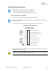
Applicator Interface Connector
Applicator Interface Connector Pin Configuration
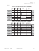
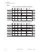
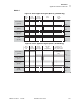
The Applicator Interface Assembly is available in two versions: a +5 V I/O and a
+24 V (24–28 V) I/O. Table 19 lists the pin configurations and functions of the applicator
interface connector for both +5 V and 24–28 V operation.
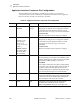
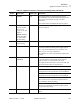
Table 19 • Applicator Interface Connector Pin Configuration
Pin No. Signal Name Signal Type Description
1 I/O SIGNAL
GROUND
I/O Signal
Ground
+5 V Version
Using jumper J5, this pin can be configured as isolated
or non-isolated from the Applicator Interface Circuit
Ground. See Table 20 on page 170 for more information.
24–28 V Version
Isolated I/O operation only. No jumpers to configure.
2+V I/O
(Fused at 1 A for
+5 V operation.
See Figure 66
on page 171 for fuse
location.)
Caution • Replace
the fuse only with
one of the same
type and rating.
Power +5 V Version
Using jumper J4, this pin can be configured as isolated
or non-isolated from the Applicator Interface Circuit
+5 V Supply. See Table 20 on page 170 for more
information.
24–28 V Version
Isolated I/O operation only. No jumpers to configure.
3 START PRINT Input Pulse Mode
The label printing process begins on the HIGH to LOW
transition of this signal if a format is ready. De-assert this
signal HIGH to inhibit printing of a new label.
Level Mode
Assert LOW to enable the print engine to begin printing
if a format is ready. The print engine prints new labels as
long as the signal is asserted. When de-asserted, the
currently printing label is completed and the print engine
stops and waits for this input to be reasserted LOW.
4 FEED Input When the print engine is in an idle state or has been
paused, assert this input LOW to trigger repeated feeding
of blank labels. De-assert HIGH to stop feeding blank
labels and register to the top of the next label.
5 PAUSE Input To toggle the current pause state, this input must be
asserted LOW for 200 milliseconds, or until the
SERVICE REQUIRED output (pin 10) changes state.